
Responsive Wearable Technology

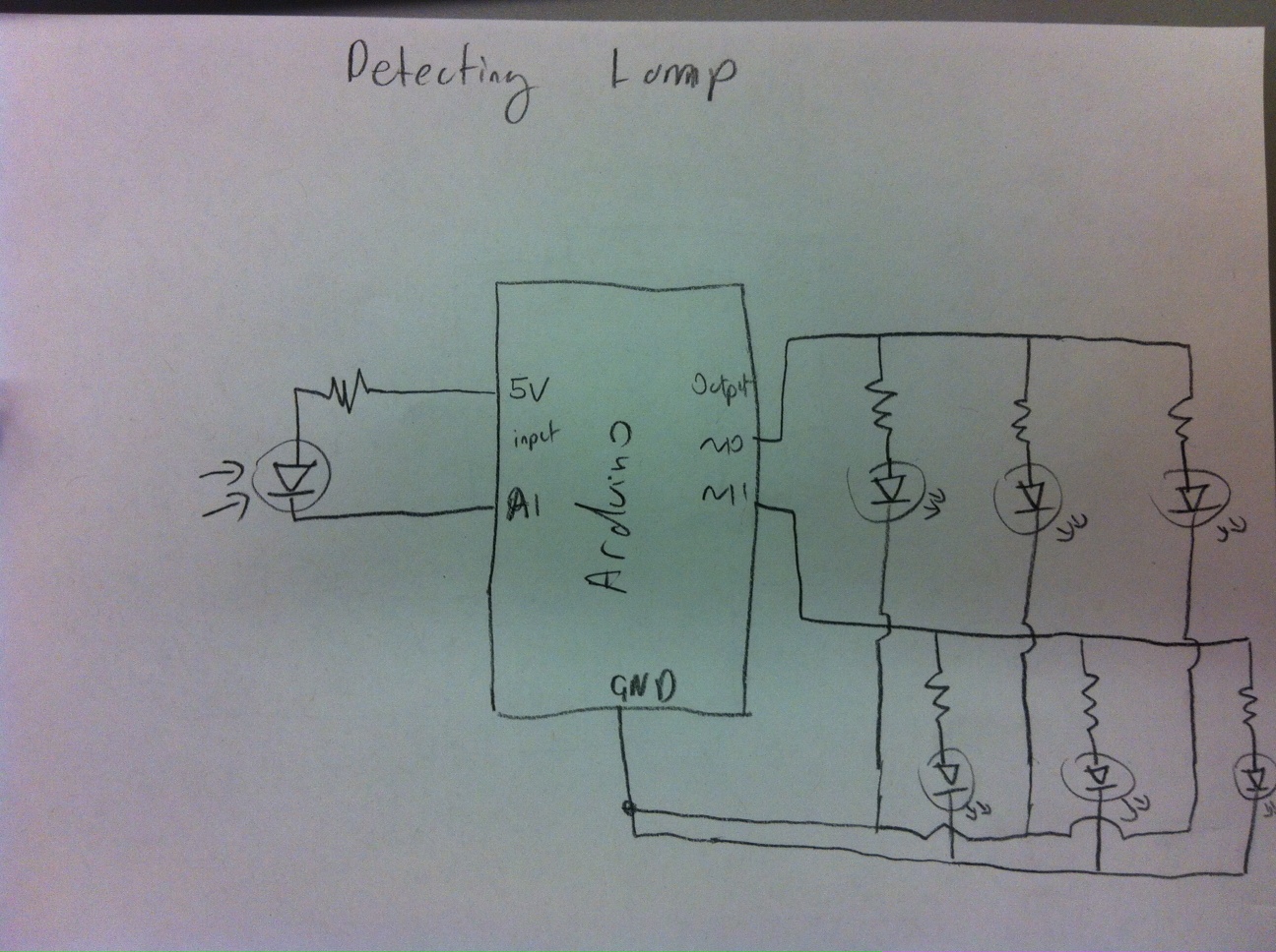
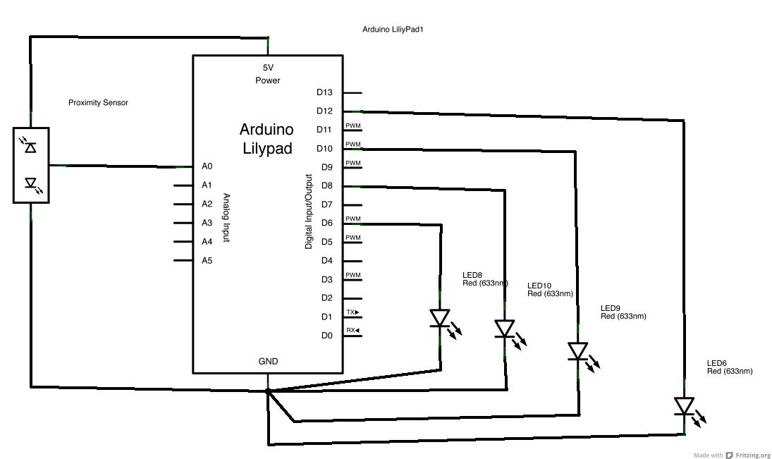
The circuit design integrates an FSR to measure pressure applied to the bottom of a bag, which can be influenced by the weight of the contents or direct pressure from fingers. The FSR operates by changing its resistance based on the force applied, enabling the system to detect varying levels of pressure. The circuit configuration includes a microcontroller to process the analog signal from the FSR, converting it into a digital signal that can be read and interpreted.
To enhance the functionality, a series of LEDs can be incorporated, programmed to light up in different sequences based on the pressure readings. For instance, the microcontroller could be programmed to activate LEDs sequentially as pressure increases, indicating different weight thresholds. This could be useful for visual feedback regarding the urgency of leaving a location, with a specific LED pattern signifying different levels of urgency.
The use of electrical tape to secure connections and prevent short-circuiting is a practical approach, ensuring the reliability of the circuit. Careful planning of the circuit layout is crucial to avoid overlaps, which could lead to unintended connections and malfunction. The decision to use fabric glue for attaching the FSR highlights the importance of selecting appropriate materials for securing components in a way that maintains functionality without compromising the integrity of the circuit.
In summary, the project demonstrates a creative application of sensor technology, exploring the interaction between physical pressure and electronic feedback. The potential for further development exists, particularly in refining the placement of the FSR for optimal performance and exploring additional functionalities that could enhance user experience.I first tried a lot of different circuit combinations with alligator clips and different interactions with code. For example, I could have them turn on individually and sequentially (A, B, C) or have them turn on sequentially but stay lit (A, AB, ABC).
I tried blinking lights as well, but it didn`t seem appropriate for the scale` concept. I planne d my circuit out so that there would be no over laps. But just to be absolutely certain, I used electrical tape to hide the circuits. It`s not the prettiest, but it`s the fastest way to prevent short circuiting. I actually had no clue how I would attach the FSR. A needle wouldn`t go through it. So I used fabric glue instead, which worked surprisingly well. Attaching conductive thread to it was a bit of a challenge too since they were so close together. The form factor of the FSR is not the best choice for what I wanted to achieve because it requires that the contents in the bag be concentrated right ON the sensor. It would be ideal if the sensor ran along the entire bottom of the bag so that the measurement of the weight is evenly distributed.
Originally, putting the sensor on the shoulder strap was an option, but because the bag I used had a skinny strap, I decided to put the FSR on the bottom of the bag instead. But in hindsight, I think the values would have read much better on the shoulder since the pressure would be more even and stable compared to random objects shuffling inside a bag.
Since applying pressure to the bottom of the bag with fingers also worked, a change of concept could be a discrete signal for a friend to leave a party early where the meter would indicate the urgency of leaving 🔗 External reference
Related Circuits

Many areas of scientific research and industrial production require vacuum conditions, where most of the air has been removed, leaving little or nothing behind. Although written specifically for home-built gas lasers, much of the following information is applicable to...

Parts List The circuit consists of a preamplifier, tone controls, and a regulated DC power supply, providing a power output of 18 Watts for an 8 Ohm load. The circuit design includes three main components: a preamplifier, tone control circuitry,...
A habit-acquisition system that tags physical objects, such as dumbbells and medicine bottles, with RF tags or microcontrollers to detect and log user interactions with these items. It includes virtual plants and creatures that simulate the health of real-world...
Alligator clips were used to construct the circuit, which was successfully operational. The code was developed, particularly focusing on the blinking section to ensure the LEDs blinked randomly rather than in a set sequence. The values read and sent...

Prototype 2 utilizes a common base to control various elements. This iteration includes a button that activates the tone only when pressed, along with a rotary potentiometer for volume adjustment. The circuit incorporates an Analog Devices ADXL3xx accelerometer that...

This document tracks the history of voltage-controlled oscillators (VCOs) since around 1910 and provides examples of VCO integration in RF integrated circuits (ICs). Voltage-controlled oscillators (VCOs) are critical components in various electronic systems, particularly in radio frequency (RF) applications. A...