
Low-frequency-transmitter
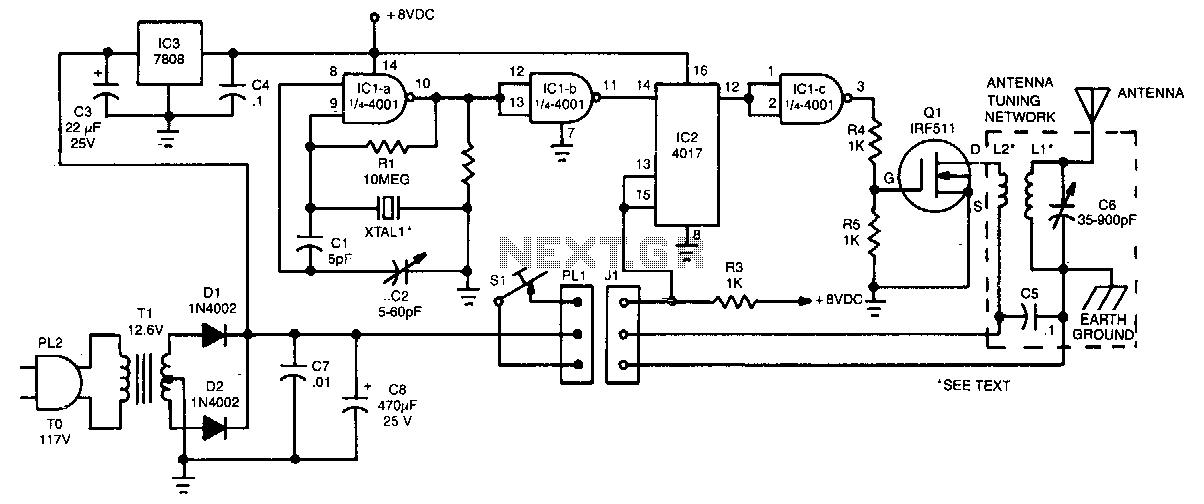
The crystal oscillator utilizes two sections of IC1, a 4001 quad 2-input NOR gate, representing a standard and reliable design. The oscillator generates a 1.85-MHz square-wave output that feeds into IC2, a 4017 divide-by-10 counter. The count enable and reset terminals, pins 13 and 15, are typically held high by resistor R3, and the counter is activated by bringing these pins low through the closure of telegraph key S1—this arrangement ensures that the final state of IC2 pin 12 remains high. The high signal on IC2 pin 12 is inverted by a third section of the 4001, IC1c, to prevent current flow through power amplifier Q1 during key-up periods.
The described circuit functions as a crystal oscillator and counter system, leveraging the characteristics of a 4001 quad 2-input NOR gate to generate a stable frequency output. The oscillator operates at a frequency of 1.85 MHz, which is determined by the crystal and the associated components in the oscillator circuit. The output from the oscillator is a square wave, suitable for digital applications, and is provided to the input of a 4017 decade counter, which divides the frequency by ten.
The counter, IC2, has its enable and reset functions controlled by pins 13 and 15, respectively. Resistor R3 plays a critical role in maintaining these pins in a high state, ensuring that the counter remains inactive until the telegraph key S1 is pressed. Closing S1 creates a low signal on both pins, thereby activating the counter. This design guarantees that the output on pin 12 of IC2 remains high when the counter is not actively counting, providing a stable signal for subsequent stages of the circuit.
The additional logic provided by the third section of the 4001 (IC1c) serves an important function during the key-up phase. By inverting the high output from IC2 pin 12, it prevents undesired current flow through power amplifier Q1, which could lead to circuit instability or damage. This feature enhances the overall reliability of the circuit during operation, particularly in telegraph applications where precise timing and signal integrity are crucial. The careful arrangement of these components ensures efficient operation and minimizes the risk of interference or malfunction, showcasing the effectiveness of this oscillator and counter design.The crystal oscillator, which uses two sections of IC1, a 4001 quad 2-input NOR gate, is a standard and reliable design. The oscillator"s 1.85-MHz, square-wave output feeds IC2, a 4017 divide-by-10 counter. The count enable and reset terminals, pins 13 and 15, are normally held high by resistor R3, and the counter is activated by bringing those pins low by closing telegraph key S1-an arrangement that guarantees that the final state of IC2 pin 12 is always high.
The high on IC2 pin 12 is inverted by a third section of the 4001, IC1c, to prevent de current flow through power amplifier Q1 during key-up periods. 🔗 External reference