
rfid with arduino

The integration of the RDM630 module into an electronic project allows for effective RFID functionality. The module operates by transmitting data in a structured format that consists of several key components. Upon receiving a signal, the module outputs a series of bytes that include a start byte, data bytes, a checksum, and an end byte. The start byte (02) indicates the initiation of data transmission, while the subsequent 10 bytes represent the RFID tag's unique identifier.
The unique ID is crucial for identifying individual RFID tags, and the data format ensures that it can be processed efficiently. The checksum, consisting of 2 bytes, serves as an error-checking mechanism to confirm the integrity of the transmitted data. The final byte (03) marks the end of the transmission, allowing the receiving system to recognize that all data has been sent.
To implement this system, the NewSoftSerial library is employed to facilitate communication between the microcontroller and the RDM630 module. By assigning specific RX and TX pins, the microcontroller can read the incoming data stream. The example code provided in the tutorial demonstrates how to capture the data, validate it against the calculated checksum, and extract the RFID tag ID for further processing.
In applications where RFID functionality is required, such as access control systems, inventory management, or asset tracking, this module provides a compact and efficient solution. The capability to connect an LED for visual feedback enhances user interaction by indicating when a signal is detected. Overall, the RDM630 module's design and the outlined methodology for data handling make it a valuable component for RFID integration in various electronic projects.If you ever wanted to integrate RFID functionality into your project, this small tutorial might help you accomplish that. I used the RDM630 module from seeedstudio in its UART version. It comes on a small board with presoldered connectors which fits perfectly on a breadboard. You only need to connect the antenna to the two pin socket. You also can connect a LED to indicate if the antenna picks up a signal. The signal output can be easily read by using the NewSoftSerial library and assigning the RX TX ports. The signal readings are transmitted in byte blocks. The first byte (02) is the start of text byte in HEX-ASCII format. Then following is the 10 byte data for the ID which has been recognized. After that a 2 byte checksum is transmitted. Followed by the last byte (03). To translate the 10 byte HEX-ASCII data to the unique ID, you only have to map the bytes to the according ASCII character.
For details have a look into the datasheet. This is an example code which checks if the data was received correctly. It prints the ID and checks if the transmitted checksum is equal to the calculated checksum of the ID. 🔗 External reference
Related Circuits
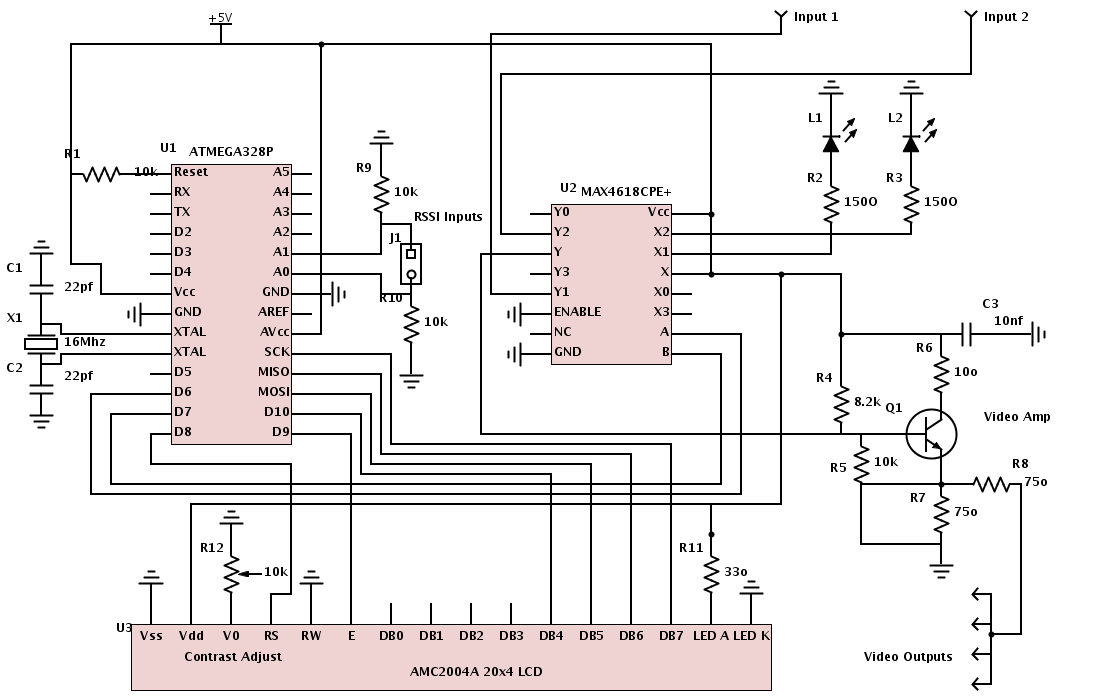
All necessary materials have been gathered to work on an Arduino-powered diversity controller. The design aims to support two inputs, although the hardware can accommodate up to four inputs, and features four amplified outputs. The diversity function will utilize...
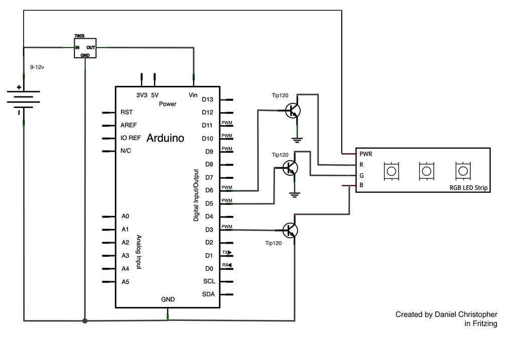
This document outlines the assembly of a circuit designed to pulse width modulate (PWM) a high-power RGB LED strip and program an Arduino to cycle through various colors. The high-power range is specified as 9-12 volts. The procedure includes...
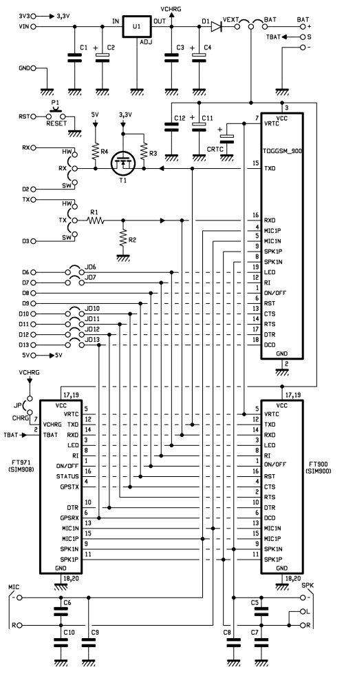
This shield for Arduino is designed based on the GSM/GPRS SIM900 module or the GSM/GPRS & GPS SIM908 module, enabling voice calls and data connections via GPRS. The supply circuit utilizes a simple LM7805 voltage regulator. To operate, it...
How to connect and program the Arduino/Atmega168 microcontroller to operate a unipolar stepper motor. To connect and program the Arduino/Atmega168 microcontroller for operating a unipolar stepper motor, the following steps should be followed: 1. **Components Required**: - Arduino or...
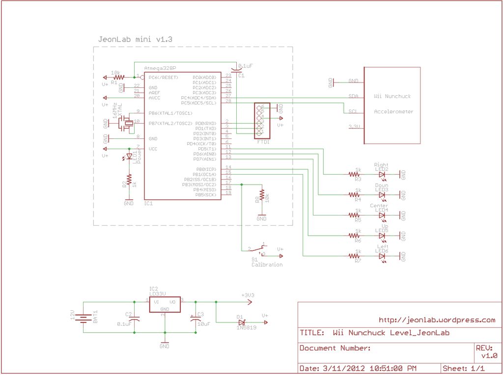
After reading an article on the Todbot blog, a purchase was made for several Wii Nunchucks from eBay. The exact amount paid is not recalled, but it was significant. The Wii Nunchuck is a motion-sensing input device that connects to...
A selection of AA batteries was acquired from a supermarket, where the packaging did not indicate the energy capacity of the products. The batteries were labeled with terms such as "PLUS," "SUPER," and "ULTRA," but lacked any measurable specifications....