
Rockwell Jupiter GPS module

The Rockwell Jupiter TU30-D140 GPS receiver module is designed for versatility in embedded applications, providing essential functionality for real-time location tracking and time synchronization. The module's compact form factor, measuring 4 by 7 cm, is suitable for integration into various electronic systems, ensuring minimal space consumption while maintaining performance.
The 20-pin connector facilitates a range of input and output signals, including power supply, serial communication, and control signals. The pinout configuration is critical for proper operation, as it allows for the connection of both active and passive GPS antennas. Active antennas benefit from a powered connection provided through the MCX connector, while passive antennas must be used without power to prevent damage. The power supply requirements specify a maximum voltage of 12V at 100mA for active antennas, while the receiver itself operates on a regulated 5V supply, highlighting the importance of adhering to these specifications for reliable performance.
The MCX connector, although less common among amateur radio enthusiasts, is a professional-grade component that ensures a secure connection to the GPS antenna. The potential for modification, such as replacing the MCX connector with an SMB connector or soldering a coaxial cable directly to the PCB, is an advanced option for experienced users. However, caution is advised due to the delicate nature of the multilayer PCB, which is not amenable to repairs.
To enhance the receiver's startup performance, a battery backup system can be implemented. This system maintains the static RAM and real-time clock functionality during power interruptions. The integration of a supercapacitor allows for data retention for extended periods, ensuring that the receiver can quickly acquire satellite signals upon power restoration. This feature is particularly beneficial in applications where power availability may fluctuate, such as in mobile or remote installations.
Communication with the module is achieved through TTL-level serial connections, requiring a TTL to RS232 level converter for compatibility with standard PC serial ports. The receiver supports NMEA0183 protocol, allowing it to interface seamlessly with a wide range of software applications designed for GPS data processing. This capability opens up various possibilities for applications, from simple data logging to complex navigation systems.
In conclusion, the Rockwell Jupiter TU30-D140 GPS receiver module offers a robust solution for embedded GPS applications, combining compact design, flexible connectivity, and reliable performance. Proper understanding of the module's specifications, power requirements, and communication protocols is essential for successful integration into diverse electronic systems.The Rockwell Jupiter TU30-D140 is a OEM (Original Equipment Manufacterer) GPS receiver module that is designed to be implemented as part of a larger design, like a vehicle tracking system, navigational system, time/clock reference etc. This is a 12 parallel-channel all-in-view receiver. The module is 4 by 7 cm, and has a 20 pins connector for the various signals and power supply`s, and a MCX connector to for the GPS antenna. In order to use the module you do not need very much: a 5V power supply, an active or passive GPS antenna and a TTL to RS232 level converter to be able to communicate with the module from a computer`s serial port. The exact specifications of the module are available in PDF format. These are on the CD if you got it with the module, or can be downloaded from the URL`s listed below. This article is meant to share the experiences with this module. I do not guarantee this information to be complete or even correct. Read the Rockwell documentation on the listed URL`s for all details! This is a right angle MCX connector, also named OSX. It is not a very familiar connector amongs radio/electronics amateurs, but is is used in professional rf designs for cellular networks.
Active GPS antenna`s are available with this MCX connector, but more often we see BNC or SMB connectors. Possibly you got a short piece of 2 mm high-quality coax with a crimped-on MCX connector with the module.
You can use it to make a BNC or SMB adapter cable. However, some care is needed. When mounting the cable to a BNC connector, the part of the cable that is not-coaxial should be kept as short as possible, and in no case longer than 2 cm. If possible, use a crimp-on BNC of SMB connector. The following is only for the experienced rf amateur. If you have the guts it is possible to remove the right-angle MCX connector and replace it with another (SMB) connector or solder a coaxial cable directly to the PCB.
The MCX connector is essentially a surface mounted device. It is soldered on the PCB with 5 points: 4 on the corners and one at the center. When you heat it up, the corners will come off, but the center conductor is not heated. For the center to come loose you will have to heat the small tip in the circle at the other side. Do not use force! The multilayer PCB is absolutely un-repairable. An active (with preamplifier) as well as a passive antenna can be used. The power supply on pin 1 of the 20-pin connector is put on the center conductor of the MCX connector, so you can use either 3. 3, 5 or 12V active antenna. I have done a simple test with a open dipole (just pull apart the screen and center of the coaxial cable over a distance of 2 * 4.
8cm) and it actually works. If you use a passive antenna, do NOT connect the antenna power supply on the module, since a passive antenne will short-circuit this power supply! On the cdrom as well as in the URL list on the end, there are some descriptions of home-brew GPS antenna.
More can be found on the Internet. It`s fun to make your own GPS antenna because of the size as well as the good results. However, keep the cable as short as possible with a passive antenna, since every bit of signal attenuation will have direct impact on the quality of the reception and thus also on the quality of the positioning calculations. This 20-pin header has all the power supply, input and output signals exept the GPS antennasignal. The header has a 2. 0 mm pitch, which is not very common. It is possible to create an adapter using a 2. 5"-to-3. 5" convertor PCB meant to connect laptop harddiscs to normal pc`s. These can be bought in PC shops for around 10 euro. This adapter needs some work before you can use it. Some points are connected together on ground, and some points are not connected at all. With a sharp knife and some short pieces of wire you can cut away the unwanted ground connections and make a 1-to-1 adapter.
2mm pitch connectors are also used for internal wiring in mouse units and floppy disc drives. Another possibility is to remove the contacts from a ic-socket, the type with tooled bus-contacts (Augat), and use these to connect wires. Or you can directly solder wires to the pins or make a special PCB. Pin 1 (square solder island) Power supply for the active antenna. This voltage is put on the center conductor of the antenna connector. Do NOT USE it with a passive antenna! Maximum of 12V @ 100mA. Most of the active antenna`s work at 5V or even 3. 3V for the newest types and consume between 15 and 50 mA. Supply for the receiver itself. Should be 5V +/- 0, 25V. The receiver consumes about 200mA. When in MR-active mode (see below) around 100mA. The absolute minimum for the receiver to operate is 4. 5V. Battery backup power input. This 3 to 5V input feeds the static ram and real-time clock chips of the module when there is no power supplied on pin 2.
Current consumption is then (and only then) between 40uA(3V) to 80uA(5V). This voltage is needed to keep the real-time clock running and static ram contents valid. This is again needed to keep te re-aquisition time as short as possible. You can use a small NICD or NIMH cell with a charging circuit, or a goldcap. A lithium cell can be used, but only if the receiver would be in operation most of the time, since the current consumption would drain a Li cell in a few weeks. There is an option to mount a supercap on the GPS board itself. It is explained elsewere on this page. Master Reset. The receiver is reset if this line is pulled to ground. As long as the line is `low` the receiver is in a low-power mode. However, low-power mode in this case still means a 100mA current consumption. These are digital inputs that define the startup mode of the receiver. These must either be connected to ground level, of pulled-up with a 10k resistor to +5V When this line is high the initial values are taken from static ram (if a battery was connected to pin 2) or from eeprom.
These initial values include the last known position and date/time, satellite orbital data, communication parameters etc. For most of the applications you will want pin 7 to be low and pin 8 to be high. The receiver will than always start in NMEA0183 mode and uses the data in sram / eeprom for the initial calculations.
See for more details the datasheet jupiter-gps-board. pdf Serial output (11) and input (12). This is the main serial port over which the application (pc, laptop, aprs etc) communicates. These lines work on TTL levels. To be able to talk with a PC you need a ttl<>rs232 converter like a MAX232 or a LT1281. Although the rs232 levels officially are +3. +12V for a "0" or "on" and -3. -12V for a "1" or "off", most of the pc`s and laptops also work fine with 5V and 0V. If you want to try this, all you need is a 74HCT04 cmos inverter and some passive components. A simple diagram is available here. An experimental setup can you see here. Serial input, also on TTL level. This port is meant for RTCM104 differential gps correction messages. No special configuration is neccesary - if valid dgps data is supplied the receiver will adjust its calculations accordingly. 1 PPS (puls per second) signal. This is a TTL signal with a frequency of exactly 1 Hz. The pulse length is exactly 25. 6 ms and the rising edge is within 1us from the UTC second transition. There is software available that synchronizes the time in your PC and that expects a 1pps signal on the DCD line, so if you make an interface yourself you could use this.
10 kHz TTL signal. This signal is also synchronous with pin 19 and has a long-term accurate to 1uHz (microhertz) or better, if the receiver has a "fix" on the GPS satellites. When the module is first used after a long time, do so with an antenna with a clear sky view. The best program to start with is a simple terminal program like Hyperterm or Teraterm. Configure the terminal program to 4800bd, no par. 8 bits, 1 stopbit and see if the receiver is producing NMEA data. It should look more or less like this: When this works you can try a more sophisticated program like VisualGPS or CSIGPS to see how the reception quality of the GPS satellites is.
Depending on a number of variables it can take a while before the receiver has determined its position, or has a `fix on the sky` as it is called in GPS jargon. These variables are: Depending on the answer on these questions the "time to fix" will vary between 20 minutes and 20 seconds.
When the energy usage of 1W is not an issue, it is best to keep the receiver powered on. However, when you use the receiver in a car you will want to switch it off, since leaving it on for a few days will most likely drain the battery. To keep the Time To Fix as short as possible after power-on, it is possible to install a supercap or goldcap on the Jupiter board.
These capacitors have a diameter of 12. 5 mm, a height of 7 mm and a pin distance of 5 mm. They are normally available in the electronics parts stores in capacity`s of 0, 1F and 0, 22F and a maximum voltage of 5. 5V. With a 0, 22F supercap the Jupiter can retain it`s data and clock for more than 48 hours, so that the receiver has a much faster fix after powerup within this time.
For a longer backup time an external Nicad or NiMh battery with a charging circuit will have to be connected to pin 3. The supercap can be mounted on the Jupiter board on position C2. This position has a square solder island and a circular one. The minus of the supercap should be connected to the circular solder island. Every program that is able to communicate with a GPS receiver in NMEA0183 mode will work with the Rockwell Jupiter receiver.
There are hunderds of application programs and hardware like APRS interfaces, LCD displays etc etc, so we won`t discuss all these here. However, some programs are specially made for the Rockwell chips Gpsmon is a DOS program that is made by Rockwell and is made specially for these modules.
It was part of the development kit. You can use the program in NMEA0183 mode as well as in Rockwell / Zodiac binairy mode. There are much more details available in the binairy mode, and it is also possible to adjust operating parameters of the receiver. This program works fine in a DOS box of windows 2k / xp. There is also a windows version Wingpsmon but I had some problems in getting this to work correctly. The manual of gpsmon is part of the acrobat document `designerguide. pdf` on the cd or on the listed URL. Tardis is a clock synchronisation program that is able to use the GPS data. It has a generic NMEA0183 mode that works with this module, but if you configure Tardis to talk to a Kallisto klok module it talks actually in the Rockwell binairy mode to the Jupiter receiver.
🔗 External reference
Related Circuits

MPEG-4 modules that achieve real-time compression and expansion, as well as network transmission of video data. The portfolio also features small camera boards equipped with an image correction function. The MPEG-4 modules are designed to handle video data efficiently, enabling...
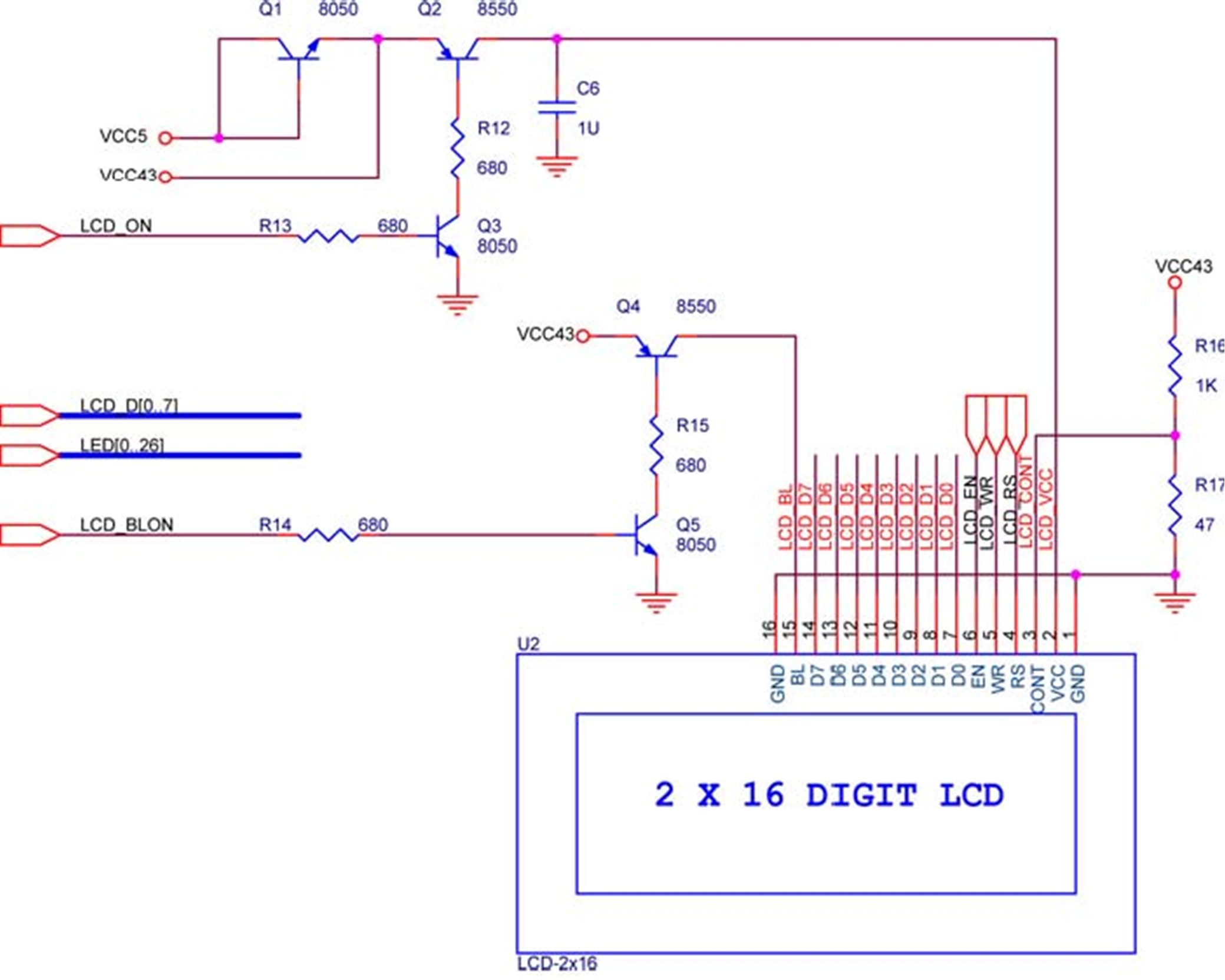
The LCD module is equipped with built-in fonts and can display text by sending the correct commands to the display controller known as HD44780. Comprehensive information regarding the usage of the display can be found in its datasheet. A...
.png)
The one-touch turn signal (OTTS) module enhances the functionality of the turn signal lever by introducing a mode where a single touch activates the indicators to blink for a specified number of times. This feature is commonly referred to...
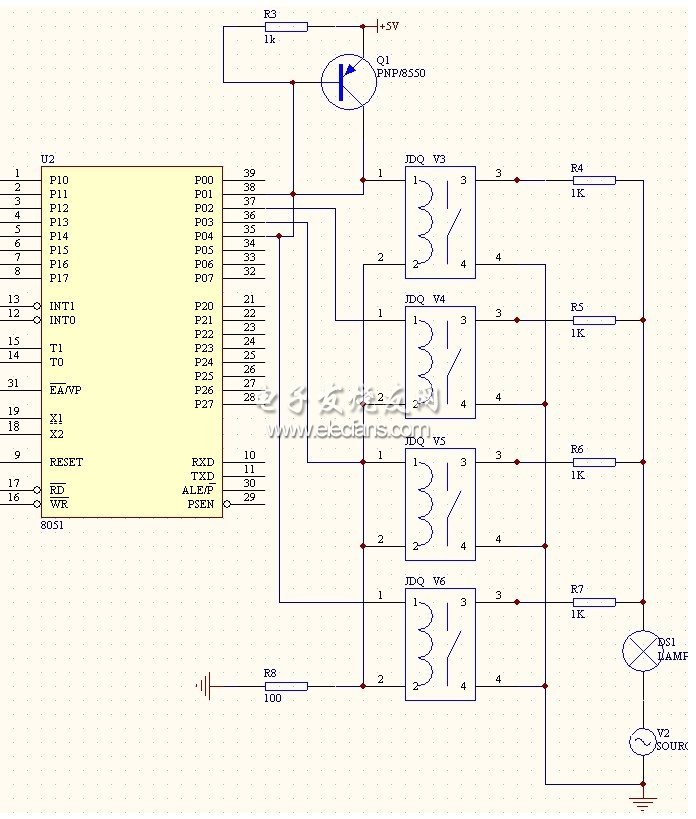
In this project, an embedded system is designed for tracking and positioning vehicles using the Global Positioning System (GPS) and Global System for Mobile Communications (GSM). The AT89S52 microcontroller interfaces with various hardware peripherals. The system continuously monitors a...
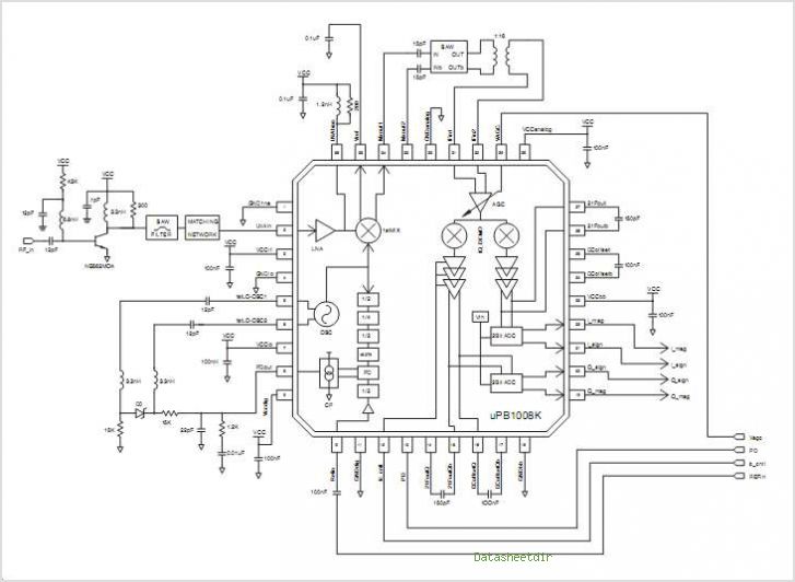
The PB1009K is a silicon monolithic integrated circuit (IC) designed for GPS receivers. This IC incorporates a complete voltage-controlled oscillator (VCO), a second intermediate frequency (IF) filter, a 4-bit analog-to-digital converter (ADC), and a digital control interface, all aimed...
This system is a control system based on a single-chip computer that allows for remote operation of lighting. The scheme primarily addresses the transmission and reception of signals, as well as program manipulation of various signals once they are...