
Room Noise Detector Circuit Schematic

The circuit operates by first capturing sound through the electret microphone, which converts acoustic energy into an electrical signal. This signal is then fed into the two operational amplifiers configured for gain, enhancing the microphone's output to a level suitable for further processing. The gain settings are adjusted based on the selected threshold level, which is determined by the position of the switch SW1.
When the microphone detects sound levels above the selected threshold, the operational amplifiers output a signal that activates the LED. The LED's flashing behavior serves as a visual alert that the noise level has surpassed the set limit, allowing users to take appropriate action if needed. The circuit is designed to be energy-efficient, consuming minimal power when idle, while providing sufficient current to the LED when it is activated.
The choice of thresholds—50 dB, 70 dB, and 85 dB—addresses various environments and user needs. For example, the 50 dB setting is particularly beneficial for nighttime monitoring in bedrooms, where excessive noise can disrupt sleep. By providing a clear visual indication of noise levels, this circuit serves as a practical tool for maintaining a conducive sleeping environment.This circuit is intended to signal, through a flashing LED, the exceeding of a fixed threshold in room noise, chosen from three fixed levels, namely 50, 70 & 85 dB. Two Op-amps provide the necessary circuit gain for sounds picked-up by a miniature electret microphone to drive a LED.
With SW1 in the first position the circuit is off. Second, third and fourth positions power the circuit and set the input sensitivity threshold to 85, 70 & 50 dB respectively. Current drawing is 1mA with LED off and 12-15mA when the LED is steady on. The 50 dB setting is provided to monitor the noise in the bedroom at night. If the LED is steady on, or flashes bright often, then your bedroom is inadequate and too noisy for sleep.
🔗 External reference
Related Circuits
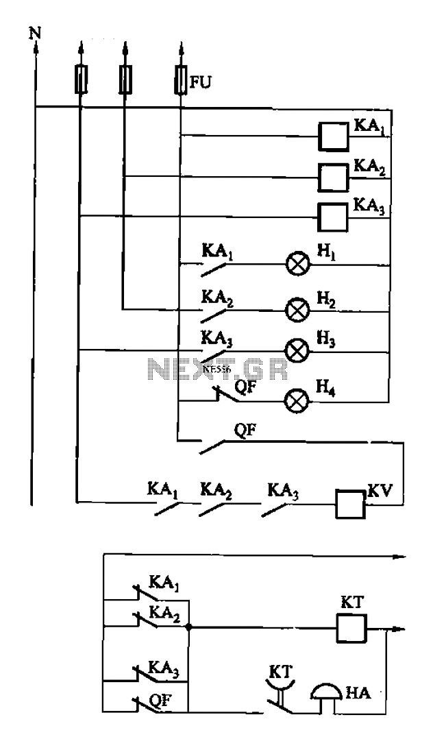
The circuit features intermediate relays KAi, KA2, and KA3, which are connected to the outlet end of the low-voltage circuit breakers. An alarm circuit is linked to a backup power supply or a battery power supply. This configuration serves...
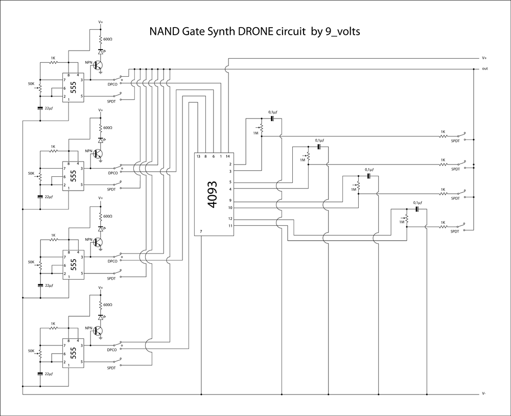
This is a brief jam session to explore the capabilities of a recently completed step sequencer. This device is quite enjoyable and expands creative possibilities. A detailed post with the circuit and instructions for building it will be provided...
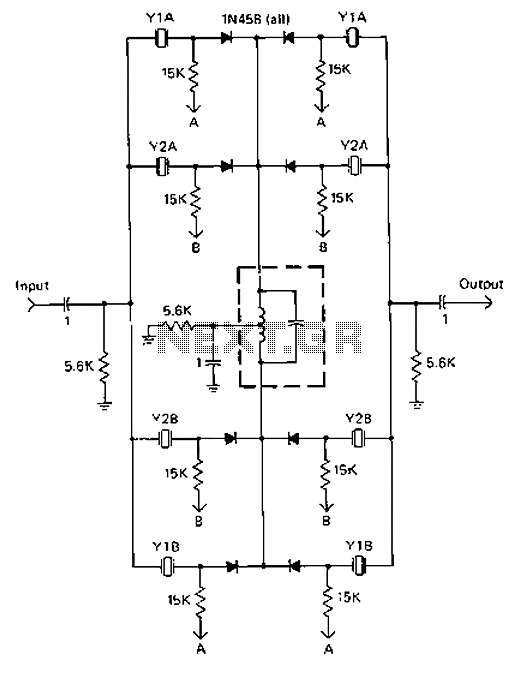
A 9-12V DC power supply is connected to control point A or point B for an amateur communication receiver IF amplifier, offering two distinct options. The power frequency is set at 455 kHz with a bandwidth of 500 Hz....
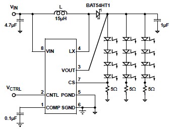
A simple white LED driver schematic can be created using the EL7513 constant current boost regulator, which is specifically designed for driving white LEDs. This driver can manage 4 LEDs in series or up to 12 LEDs in a...
A small electronic switch connects a battery to equipment for a specific duration when a push-button is momentarily pressed. The circuit also considers ambient light levels; when it is dark, the display cannot be read, so it is logical...
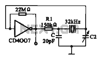
A 32 kHz clock oscillator is essential for digital circuits, as depicted in the schematic. The 32 kHz crystal clock oscillator serves to provide a time reference signal for the digital circuit. It utilizes a CMOS integrated circuit, specifically...