
RS232 Connections wiring up
In a typical serial communication setup, the essential connections include Transmit (Tx), Receive (Rx), and Ground. However, many driver software implementations require handshaking signals such as Request to Send (RTS) and Clear to Send (CTS) to function correctly. If these handshaking lines are not actively used in a particular application, they can be left unconnected, which may lead to unpredictable behavior during communication.
To ensure reliable operation, a common practice is to implement a loopback configuration for the handshaking lines. This involves connecting the RTS pin to the CTS pin, effectively simulating the presence of a responding device. This loopback arrangement allows the driver software to detect the correct signal levels on the handshaking lines, thus preventing it from waiting indefinitely for a response that will never arrive.
In practical terms, a simple circuit can be constructed using a DB9 or DB25 connector, which is commonly used for serial connections. The Tx and Rx lines are connected to the respective pins on the connector, while the Ground is connected to the common ground pin. The RTS and CTS lines are then connected directly to each other. This configuration ensures that any data transmitted from the Tx line can be received on the Rx line without the need for an external device, while the handshaking signals are appropriately managed.
For applications that require additional robustness, it may also be beneficial to include pull-up or pull-down resistors on the handshaking lines to ensure that they maintain a defined state when not actively driven. This can further enhance the reliability of the communication setup, especially in environments with electrical noise or interference.
Overall, implementing a loopback for the handshake lines in a serial communication circuit provides a straightforward and effective solution to ensure compatibility with driver software, allowing for seamless operation even in the absence of external devices.While the normal PC hardware might well run with just Tx, Rx and Ground connected, most driver software will wait forever for one of the handshaking lines to go to the correct level. Depending on the signal state it might sometimes work, other times it might not. The reliable solution is to loop back the handshake lines if they are not used. 🔗 External reference
Related Circuits
1997 Toyota Camry Fuel Pump Wiring Diagram. The fuel pump wiring diagram for the 1997 Toyota Camry provides a detailed representation of the electrical connections associated with the vehicle's fuel pump system. This diagram typically includes the power supply lines,...
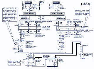
The part of the 1995 Ford Ranger wiring diagram includes components such as the transmission range sensor, electronic engine control, clutch pedal position switch jumper, speed control, automatic transmission, starter interrupt relay, relay box, starter motor during engine starting,...
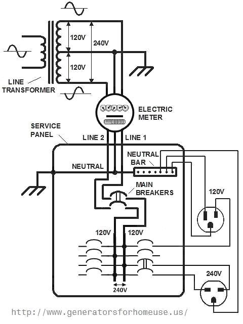
When considering a backup power system, adding an electric circuit, or installing a new appliance, it is crucial to understand the basics of home electrical wiring and the applicable codes. First, it is important to review how electricity reaches...
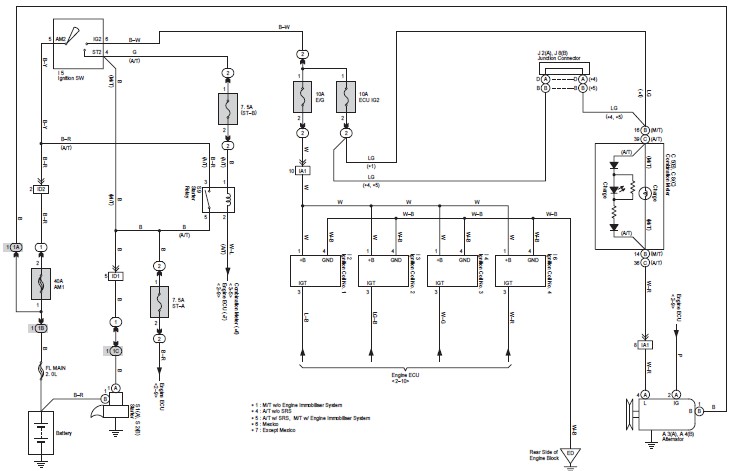
This document contains the complete wiring diagram for the Toyota Avanza. It is highly useful for technicians and car owners during service or maintenance activities. The wiring diagram includes the wiring for the Front Wiper and Washer, Headlight, ABS,...
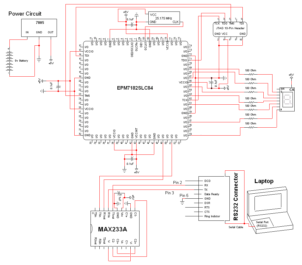
The schematic for this project is a modified version of the CPLD development board schematic. Several new components have been added for this project, and the completed schematic can be viewed below. The main components in the schematic are...
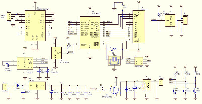
This is the fully featured, jammed packed temperature readout unit. I can measure temperature from up at 8 DS1820 digital temperature sensors all on the same 1-wire bus. That's right only 3 wires are needed to go to all...