
Salt TasterCircuit

The circuit operates on the principle that the resistance of the liquid changes with varying salt concentrations. The use of IC1A as a differential amplifier allows for sensitive detection of these changes. The output from IC1A is fed into the comparator stages (IC1B, IC1C, and IC1D), which are set to specific thresholds corresponding to different salt concentration levels. The LEDs provide a visual representation of the salt concentration, making it user-friendly for individuals monitoring dietary salt intake.
The reference voltages established by D1 and D2 are crucial for maintaining accuracy in the readings. The resistor chain connected to D2 ensures that the comparators operate within a defined voltage range, enhancing the reliability of the circuit. The setup trimmer R4 allows for fine-tuning of the probe sensitivity, accommodating variations in probe construction and liquid properties.
The design of the probe using a mono jack plug is particularly advantageous due to its simplicity and cost-effectiveness. The insulation method described ensures that the probe can be easily fabricated while maintaining consistent measurements. The choice of container for testing (the cylindrical plastic cap) is practical, providing a controlled environment for the liquid sample.
Overall, this circuit provides a straightforward and effective solution for measuring salt content in liquids, making it suitable for dietary applications and other scenarios where salt concentration monitoring is necessary.This circuit was designed to detect the approximate percentage of salt contained in a liquid. After careful setting it can be useful to persons needing a quick, rough indication of the salt content in liquid foods for diet purposes etc. IC1A op-amp is wired as a DC differential amplifier and its output voltage increases as the DC resistance measur
ed across the probes decreases. In fact, fresh water has a relatively high DC resistance value that will decrease proportionally as an increasing amount of salt is added. IC1B, IC1C and IC1D are wired as comparators and drive D5, D4 and D3 in turn, as the voltage at their inverting inputs increases.
Therefore, no LED will be on when the salt content of the liquid under test is very low, yellow LED D5 will illuminate when the salt content is low, green LED D4 will illuminate if the salt content is normal and red LED D3 will illuminate if the salt content is high. D1 and D2 are always on, as their purpose is to provide two reference voltages, thus improving circuit precision.
At D2 anode a stable 3. 2V supply feeds the non-inverting inputs of the comparators by means of the reference resistor chain R8, R9 and R10. The 1. 6V reference voltage available at D1 anode feeds the probes and the set-up trimmer R4. One of these two red LEDs may be used as a pilot light to show when the device is on. It was found by experiment that a good and cheap probe can be made using a 6. 3mm. mono jack plug. The two plug leads are connected to the circuit input by means of a two-wire cable (a piece of screened cable works fine).
The metal body of the jack is formed by two parts of different length, separated by a black plastic ring. You should try to cover the longest part with insulating tape in order to obtain an exposed metal surface of the same length of the tip part, i.
e. about 8 to 10mm. starting from the black plastic ring. In the prototype, three tablespoons of liquid were poured into a cylindrical plastic cap of 55mm. height and 27mm. diameter, then the metal part of the jack probe was immersed in the liquid. 🔗 External reference
Related Circuits
Detects the amount of salt contained in liquid foods, featuring a three-level LED indicator. This circuit is designed to detect the approximate percentage of salt concentration. The salt detection circuit operates by utilizing a conductivity sensor that measures the ionic...

This circuit is designed to detect the approximate percentage of salt contained in a liquid. After careful calibration, it provides a quick, rough indication of the salt content in liquid foods for dietary purposes. The circuit utilizes the LM324...
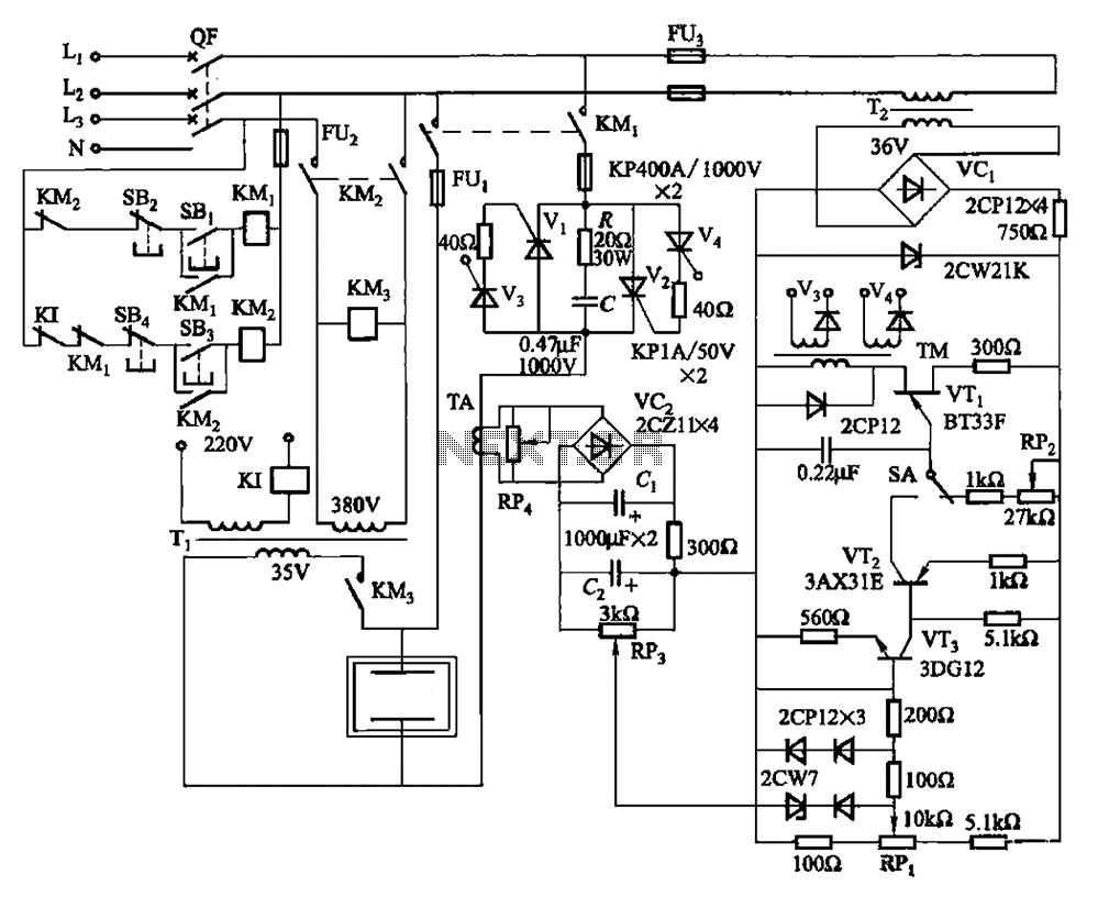
80 kW resistance salt bath furnace control circuit. The salt bath resistance furnace is a high-power device that employs fast start and temperature control technology to significantly save energy. The circuit includes a single-junction transistor (VTi) used as a...