
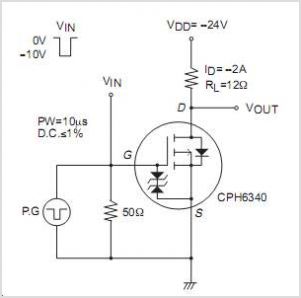
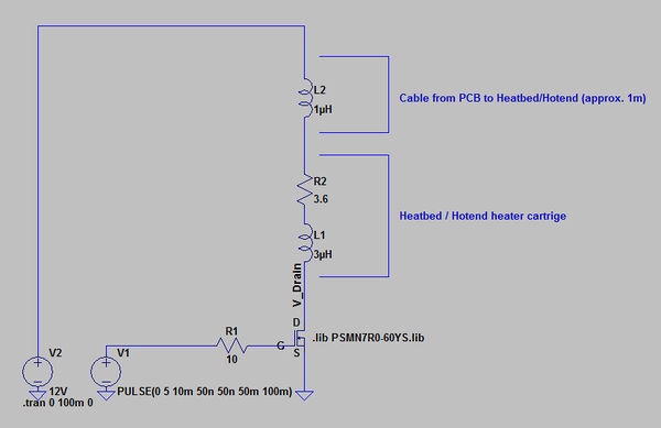
Saturating a N-Channel MOSFET

The circuit in question involves several critical components that must be carefully selected and configured to ensure reliable operation. The transistor requires a minimum gate voltage of 2 volts to begin conducting, but to achieve full saturation, a higher voltage may be necessary. This can typically be determined by consulting the transistor's datasheet, which provides information on the gate-source voltage (Vgs) required for full enhancement mode operation.
To connect the 5V GPIO pin to the gate of the transistor, a resistor is needed to limit the current flowing into the gate. The value of this resistor can be calculated using Ohm's Law, factoring in the desired gate current and the voltage drop across the resistor. It is advisable to choose a resistor value that allows sufficient gate current while preventing excessive current that could damage the GPIO pin.
The diode selected for the circuit must be capable of handling the inductive kickback generated by inductive loads. The specified diode, rated for 1000 volts and 1 amp, appears suitable for many applications; however, the specific load characteristics must be considered to ensure that the diode can safely handle the peak reverse voltage and current during operation.
Regarding the 7805 voltage regulator, it is essential to implement proper input and output filtering to prevent damage and ensure stable output voltage. A rectifier is needed to convert AC voltage from the transformer to DC voltage, followed by a bulk capacitor to smooth out fluctuations in the rectified voltage. The capacitors recommended in the 7805 datasheet should be included to maintain stability and transient response.
In summary, careful attention must be given to the selection of the transistor, resistor, diode, and voltage regulator components, along with their configuration, to achieve a robust and functional circuit design. Proper calculations and adherence to component specifications will help ensure reliable performance and longevity of the circuit.It needs 2 volts as its threshold however, that only allows a small amount of curent to flow through the transistor. How do I know how much voltage I need to make it fully on. Also, how do I determine what type of resistor to use from the 5V GPIO pin to the gate of the transistor.
My other question is what do I need to look at to make sure the diode is strong enough to handle the EMF kickback. The diode I am looking at is from Jameco with model number 1000 VOLT 1 AMP SILICON RECTIFIER DIODE. VERY IMPORTANT: You connected a transformer directly to 7805 regulator! There is a good chance that such setup will destroy everything to the right side of the transformer. You need a rectifier, a bulk capacitor and capacitors recommended in the 7805`s datasheet for this to work correctly. If the transformer is there to represent wall-wart which outputs DC voltage, than it`s safe, but capacitors small capacitors for 7805 will still be needed for good operation.
AndrejaKo Mar 8 `13 at 19:00 @jippie: There are a lot of things to discuss with this circuit, so I`d rather not split the question into lots of pieces. That will make is harder to see the whole picture. Think of this more as a design review question than specifically about the FET and a diode. Olin Lathrop Mar 8 `13 at 19:17 🔗 External reference
Related Circuits
The CS4328 is a complete stereo digital-to-analog output system. In addition to the traditional D/A function, the CS4328 includes an 8 digital interpolation filter followed by a 64 oversampled delta-sigma modulator. The modulator output controls the reference voltage input...
The Electronics Schematic Diagram MJR7-Mk3 Mosfet MJR6 page includes distortion extracted using the nulling method with a speaker load and a music signal to demonstrate that these designs have no audible distortion in normal use. The MJR7 has even...
The circuit incorporates components Q, C, and ZD, which are responsible for the bias and buffer stages. Its primary objective is to ensure stable MOSFET gate operation and provide an offset voltage through a voltage buffer amplifier stage with...
Two working examples have been assembled, one utilizing a PNP and an NPN transistor, and the other employing two MOSFETs. Both circuits function correctly, but as anticipated, the MOSFET circuit draws significantly less current (0.1 mA compared to 4.5...
The primary concern is that the RDS_on of the utilized MOSFETs, when driven with a 5V gate voltage, is excessively low. Additionally, the reverse voltage that occurs when the MOSFET transitions from the on to the off state can...
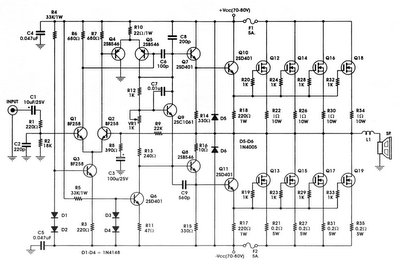
Currently, a basic MOSFET amplifier or power amplifier is designed to deliver an output power of ±100 Watts RMS with an 8 Ohm load, or ±160 Watts RMS with a 4 Ohm load. The simplicity of this circuit results...