
Schematic Diagram DCF77 Preamplifier circuit and explanation

The radio-controlled clock project involves several critical components and stages that ensure effective reception and decoding of the DCF77 time signal. The heart of the system is the microcontroller, which is programmed to interpret the time data received from the DCF77 signal. The receiver module, typically a compact board, integrates a ferrite antenna designed to capture the low-frequency signal effectively.
The preamplifier stage is vital in enhancing the signal strength before it reaches the microcontroller. The source follower (T1) acts as a buffer, ensuring that the resonant circuit retains its quality without significant damping. The bipolar transistor (T2) amplifies the signal by approximately 5 dB, which is crucial for maintaining the integrity of the time signal, especially in areas with weaker reception.
The transformer plays a dual role in the circuit: it couples the amplified signal to the DCF77 module while also contributing to the resonant circuit formed with capacitors C4 and C5. This resonant circuit must be finely tuned to match the carrier frequency of 77.5 kHz for optimal performance. The use of an oscilloscope during this tuning process allows for real-time monitoring of the output signal, ensuring precise adjustments can be made to achieve the best possible signal amplitude.
The choice of transformer is also critical; the FT50-77 core is specifically designed to facilitate resonant circuit applications at the desired frequency. The winding configuration (two 57-turn windings) is essential for achieving the necessary inductance. If a transformer with an adjustable core is used, it offers an alternative means of fine-tuning the resonant frequency, potentially simplifying the design by negating the need for trimmer capacitors.
Overall, this project combines microcontroller programming, RF engineering, and circuit design to create a reliable and functional radio-controlled clock, demonstrating the intersection of various electronic principles and practices.A popular project among microcontroller aficionados is to build a radio-controlled clock. Tiny receiver boards are available, with a pre-adjusted ferrite antenna, that receive and demodulate the DCF77 time signal broadcast from Mainf lingen in Germany. DCF77 has a range of about 1, 000 miles. All the microcontroller need do is decode the signal and output the results on a display. The reception quality achieved by these ready-made boards tends to be proportional to their price. In areas of marginal reception a higher quality receiver is needed, and a small selective preamplifier stage will usually improve the situation further. The original ferrite antenna is desoldered from the receiver module and connected to the input of the preamplifier.
This input consists of a source follower (T1) which has very little damping effect on the resonant circuit. A bipolar transistor (T2) provides a gain of around 5 dB. The output signal is coupled to the antenna input of the DCF77 module via a transformer. The secondary of the transformer, in conjunction with capacitors C4 and C5, forms a resonant circuit which must be adjusted so that it is centered on the carrier frequency.
An oscilloscope is needed for this adjustment, and a signal generator, set to generate a 77. 5 kHz sine wave, is also very useful. This signal is fed, at an amplitude of a few milli-volts, into the antenna input. With the oscilloscope connected across C4 and C5 to monitor the signal on the output resonant circuit, trimmer C5 is adjusted until maximum amplitude is observed. It is essential that the transformer used is suitable for constructing a resonant circuit at the carrier frequency.
Our proto-type used a FT50-77 core from Amidon on which we made two 57-turn windings. It is also possible to trim the resonant frequency of the circuit by using a transformer whose core can be adjusted in and out. In this case, of course, the trimmer capacitor can be dispensed with. 🔗 External reference
Related Circuits
GND and VCC are positioned perpendicularly to the other pins in the circuit diagrams, while the actual Z80 is a DIP with no pins in these locations. This arrangement complicates the readability of the circuit diagram, necessitating a mapping...

This design circuit is for a temperature sensor that utilizes an LM335 integrated circuit (IC) to convert ambient temperature into an equivalent output voltage. The output voltage of the LM335 increases by approximately 10 mV for every 1 degree...
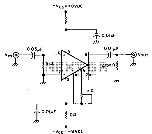
This circuit provides approximately 20 dB of voltage gain with a frequency range from 0.5 to 50 MHz. The low-frequency response of this circuit can be extended by increasing the value of the 0.05 µF capacitor or by removing...
The output voltage is = 0.707 x Vin, at the center position. The output voltage is = Vin, at either extreme position. This circuit appears to describe a variable output voltage system, likely utilizing a potentiometer or a similar adjustable...
Dodge Durango Fog Light Wiring Diagram. The Dodge Durango fog light wiring diagram provides a visual representation of the electrical connections and components involved in the fog light system of the vehicle. This diagram typically includes the battery, fog light...
The circuit below requires a double pole, double throw relay in conjunction with a single transistor to allow toggling the relay with a momentary push button. One set of relay contacts is used to control the load, while the...