
Schematic diagram for the One Transistor FM Radio with Improved Audio Gain

To implement the described circuit modifications, the variable capacitor (C3) must be configured in a series arrangement to enhance tuning linearity. This configuration utilizes the outer terminals of C3, effectively bypassing the central lead to provide a more stable tuning range. The gain achieved through this setup is adequate for driving standard earphones; however, users situated at a considerable distance from broadcasting stations may experience challenges in audio clarity and volume.
The absence of an external antenna option presents limitations in reception capabilities. An external antenna would necessitate the integration of an additional transistor to amplify the incoming signal. For users seeking to improve audio performance, especially in cases where the TL431CLP chip is not accessible, alternative audio amplification solutions are recommended. The LM386 and TDA7052 amplifiers are both viable substitutes that can be integrated into the design.
In the case of the TDA7052, the Quasar DIY project kit #3027 serves as a comprehensive solution, offering all necessary components for assembly. This kit is particularly suitable for users who require a straightforward application of the TDA7052 amplifier, ensuring compatibility and ease of use within the existing circuit framework. The integration of these components will enhance audio output, making the overall system more effective for various listening environments.Connect the two sections of the variable capacitor (C3) in series to linearize the tuning somewhat. That is, use the connections on either end of C3 and don`t use the middle lead. The gain is just enough to drive an earphone. If you live too far away from radio stations, you might have trouble hearing one. There is no option here for an external a ntenna (that would require and extra transistor). If you want a little more audio gain, or you cannot locate a TL431CLP chip, you can use some other audio amplifier in the circuit where pins 1 and 2 of D1 normally connect. You can use an LM386 or a TDA7052 audio amplifier. Quasar DIY project kit #3027 is a complete TDA7052 audio amplifier kit and it works fine in this application.
🔗 External reference
Related Circuits
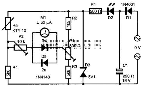
The telephone line tester comprises a meter used to measure line voltage in both the on-hook and off-hook states, three resistors (including one variable resistor), a pushbutton switch, and a modular telephone connector. When the circuit is connected to...

This design circuit is for a stereo amplifier intended for a high-sensitivity stereo parabolic microphone, enabling the listening of distant sounds. Unlike typical parabolic microphones that are monophonic, this unit features a stereo audio path, resulting in more realistic...
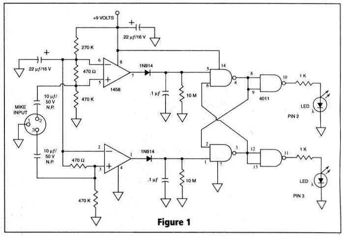
Many things can go wrong in a modern recording studio, but few are as difficult to track down as reversed microphone polarity. When a microphone is placed in front of a sound source, a positive pressure on its diaphragm...
A long time ago, when telephones were simple and reliable from an electrical standpoint, telecom operators installed surge protection on all telephone lines exposed to storm risks. Paradoxically, with the advent of delicate and expensive equipment such as electronic...
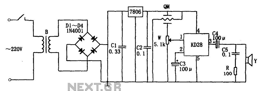
The system includes a gas-sensitive sensor element QM (type QM-N5), a buck rectifier, and regulator circuits, integrated circuits KD28, a speaker Y, and other components. The buck regulator circuit features a transformer rectifier and a bridge rectifier comprising diodes...
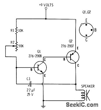
R2 controls the charging speed of capacitor C1. At a specific charge level, C1 triggers transistors Q1 and Q2, which release a 9-volt pulse. This pulse generates a clicking sound. The discharge process of the capacitor involves it charging...