
Scmitt Trigger circuit using NE 555

The 555 timer's versatility extends beyond simple timing applications, allowing for the implementation of various signal processing functions. In the Schmitt Trigger configuration, the two comparators provide hysteresis, which enhances the noise immunity of the circuit by ensuring that the output state changes only when the input signal crosses specific threshold levels. This is particularly useful in digital signal processing where clean transitions between high and low states are necessary.
The voltage divider formed by R1 and R2 determines the precise biasing point at 1/2 Vcc, which is critical for the proper operation of the Schmitt Trigger. The choice of resistor values affects the response time and the stability of the output. For instance, increasing the resistance values will slow down the response time, while decreasing them will result in a faster response but might introduce instability if the values are too low.
The capacitor C1 plays a crucial role in shaping the input signal. By selecting a smaller capacitance value, the circuit can effectively differentiate fast-changing signals, making it suitable for applications requiring rapid signal processing. The combination of C1 with R1 and R2 creates a high-pass filter effect, allowing only the high-frequency components of the input waveform to pass through. This characteristic is particularly beneficial for applications such as pulse-width modulation (PWM) and signal conditioning.
Overall, the 555 timer in a Schmitt Trigger configuration is a powerful tool for engineers, enabling the design of robust and efficient digital circuits capable of handling various input signal conditions.Apart from the timing functions, the two comparators of the 555 timer can be used independently for other applications. One example is a Schmitt Trigger shown here. The two comparator inputs (pin 2 & 6) are tied together and biased at 1/2 Vcc through a voltage divider R1 and R2.
Since the threshold comparator wil trip at 2/3 Vcc and the trigger comp arator will trip at 1/3Vcc, the bias provided by the resistors R1 & R2 are centered within the comparators trip limits. By modifying the input time constant on the circuit, reducing the value of input capacitor (C1) to 0.
001 uF so that the input pulse get differentiated, the arrangement can also be used either as a bistable device or to invert pulse wave forms. In the later case, the fast time combination of C1 with R1 & R2 causes only the edges of the input pulse or rectangular waveform to be passed.
These pulses set and reset the flip-flop and a high level inverted output is the result. 🔗 External reference
Related Circuits
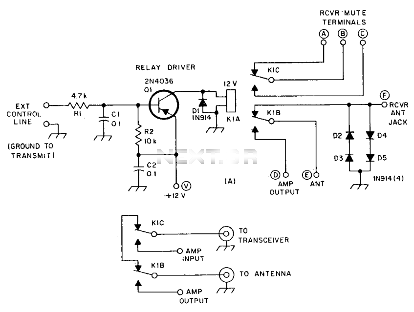
R1 and R2 are carbon composition resistors labeled as Va or Vi. K1 is a 12 V DPDT DIP relay. Illustration A demonstrates the connection of the relay contacts for use with a separate transmitter-receiver combination. The circuit is...
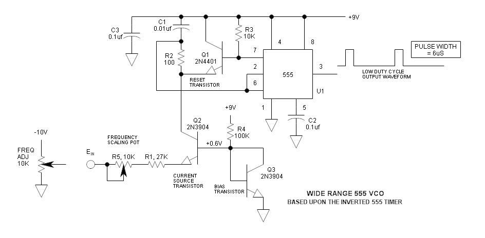
The frequency of the 555 timer can be adjusted by changing the voltage at pin 5. However, the range and linearity of this adjustment are quite limited. This can be significantly improved by using an inverted 555 timer circuit....
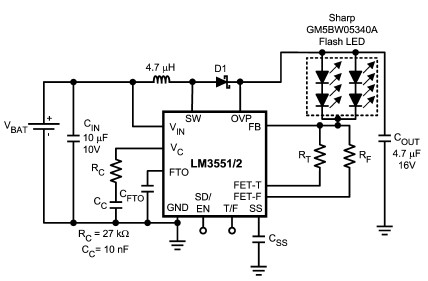
The LM3551 and LM3552 are fixed frequency, current mode step-up DC-DC converters featuring two integrated NFETs. These devices facilitate the design of a straightforward and highly precise LED brightness control system. They are capable of driving loads up to...
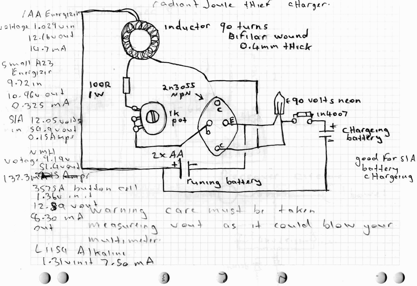
A high power joule thief circuit is explained in this post, which can be constructed by any new hobbyist. Here is the simplified drawing of the radiant joule thief battery charger. The inductor was wound with many turns until...

This filter circuit, which utilizes the LM1458 or a similar operational amplifier, has a frequency response ranging from 300 Hz to 3.4 kHz, exhibiting a roll-off of 12 dB per octave outside the passband. Section A serves as the...
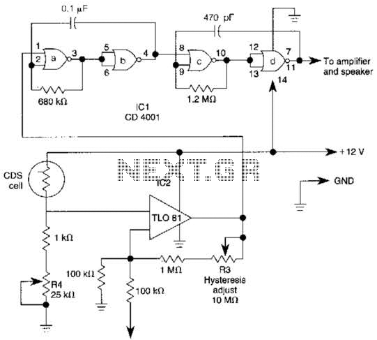
The TL081 is utilized as a comparator within a Wheatstone bridge circuit. When the resistance of the CDS cell decreases due to light exposure, the output from IC2 prompts the low-frequency oscillators (a) and (b) to produce a 10-Hz...