Scr-replacing-latching-switch

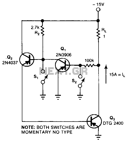
This circuit provides the turn-on characteristics of a Silicon Controlled Rectifier (SCR) but allows for easy turn-off. The switch consists of three transistors with decreasing current ratings: Q3 has a high current rating, while Q2 has a medium rating. The current to be switched is 15 A. Momentarily pressing S2 removes the base drive from Q1, turning it off and allowing Q2 to turn on. Q2 then drives the base-emitter junction of Q3, turning Q3 on. The collector-emitter voltage of Q3, which serves as the base drive for Q1, is essentially zero, keeping Q1 off. To turn Q3 off, pressing S1 momentarily shunts the base current of Q2 to ground, reversing the sequence that turned Q3 on.
This circuit operates as a controlled switch using a combination of transistors to manage the switching of a high current load. The design leverages the properties of transistors to create a cascading effect, where the state of Q1 influences the operation of Q2 and Q3.
The circuit begins with Q1, which initially provides base drive to Q2. When the switch S2 is pressed, it interrupts the base drive to Q1, causing Q1 to turn off. This action allows Q2 to activate, which then provides the necessary base drive to Q3. The ability of Q3 to handle high current is crucial for applications requiring the switching of 15 A, as it ensures that the circuit can manage significant loads without overheating or failing.
Once Q3 is activated, its collector-emitter voltage drops to near zero, effectively cutting off the base drive to Q1. This feedback mechanism ensures that Q1 remains off while Q3 is conducting, creating a stable on-state for the circuit.
To de-energize the system and turn off Q3, the operator can press switch S1. This action temporarily diverts the base current from Q2 to ground, removing its drive and consequently turning off Q3. With Q3 deactivated, the chain reaction reverses, allowing Q1 to regain its base drive and turn back on if necessary.
This design showcases an efficient method for controlling high currents with low control signals, demonstrating the versatility and reliability of transistor-based switching circuits in electronic applications.This circuit provides the tum-on characteristics of an SCR, but turns off with ease. The switch is comprised of three transistors with descending current ratings: Q3 has a high-current rating and Q2 has a medium rating. The current, !1, to be switched is 15 A. Momentarily depressing S2 removes Ql"s base drive, turning Ql off and allowing Q2 to tum on. Q2 then drives the base-emitter junction of Q3, turning Q3 on. Q3"s collector-emitter voltage, which ·serves as Ql"s base drive, is essentially zero, keeping Ql off. To tum Q3 off, depress Sl; this action momentarily shunts Q2"s base current to ground, reversing the chain of events that turned Q3 on.