
Rf sniffer

The described circuit serves as an RF signal detector, capable of operating across a wide frequency range, specifically from below the standard broadcast band up to frequencies exceeding 500 MHz. This versatility allows it to detect a variety of signals, making it suitable for applications in communication systems, hobbyist projects, and educational demonstrations.
The core component of the circuit is the pick-up diode, designated as D1. This diode functions as the primary sensor for RF signals. The diode's sensitivity can be finely tuned using a variable resistor, R2, which adjusts the biasing conditions of D1. By modifying the resistance value of R2, the circuit can be optimized to respond effectively to both weak and strong RF signals. This feature is particularly important in environments where signal strength may vary significantly.
When an RF signal is detected, the circuit activates an LED to provide a visual indication of the signal's presence. The LED's brightness correlates with the strength of the received signal, allowing users to gauge the signal intensity. Additionally, a Piezo sounder is integrated into the circuit to produce an audible alert. The sound output is designed to be faint, providing a subtle indication that complements the visual feedback from the LED.
To achieve maximum sensitivity, it is crucial to carefully adjust R2. The optimal setting is reached when the LED begins to emit light and the Piezo sounder generates a faint sound, indicating that the circuit is responsive to incoming RF signals. This sensitivity adjustment allows the user to tailor the circuit's performance based on specific operational requirements or environmental conditions.
Overall, this RF signal detection circuit is a valuable tool for identifying and monitoring RF signals across a broad frequency spectrum, combining visual and auditory feedback to enhance user experience and effectiveness.This circuit responds to RF signals from below the standard broadcast band to well over 500 MHz, and provides a visual and audible indication when a signal is received. The circuit is designed to receive low-powered signals as well as strong sources of energy by adjusting the bias on the pick-up diode, Dl, with R2.
A very sensitive setting can be obtained by carefully adjusting R2 until the LED just begins to light and a faint sound is produced by the Piezo sounder.
Related Circuits
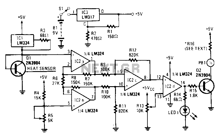
The sensing element Q1 is a 2N3904 general-purpose NPN transistor, although any general-purpose NPN unit in a TO-92 style case will suffice. IC1, an LM334, provides Q1 with a constant current that remains stable regardless of temperature variations. An...
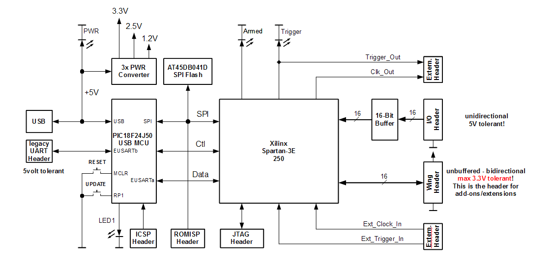
The Openbench Logic Sniffer is an open-source logic analyzer designed to support the SUMP logic analyzer software at minimal cost. Source and design files can be downloaded from the Gadget Factory project page. This project originated from discussions in...
.png)
This document describes a simple engineering project circuit for a mobile cell phone detector (sniffer). This compact mobile communication detector can sense the presence of a mobile device, making it suitable for preventing mobile phone usage in private spaces,...