
Self-powered Sine to Square wave Converters

This circuit operates on the principle of signal conversion, leveraging a voltage doubler configuration to harness energy from the input sine wave. The capacitors C1 and C2, along with diodes D1 and D2, function as a rectifying and energy-storing mechanism, effectively doubling the voltage of the input signal. This increased voltage is crucial for powering the integrated circuit (IC) without the need for an external power supply, making the circuit highly efficient and portable.
The operational amplifier IC1A plays a vital role in amplifying the sine wave input, enhancing its amplitude to ensure that subsequent processing stages receive a robust signal. The inverters within the IC are configured to transform the amplified sine wave into a square wave. This transformation is characterized by maintaining a consistent mark/space ratio, which is essential for applications requiring precise timing and signal integrity.
The circuit is capable of operating effectively across a frequency range of 20Hz to 20kHz, making it suitable for various applications, including testing and signal generation in audio and communication systems. The design emphasizes fast rise and fall times, which are critical for minimizing distortion and ensuring the square wave output closely resembles an ideal square wave. This feature enhances the circuit's performance in real-world applications, where signal fidelity is paramount.
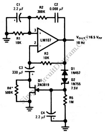
Overall, the described circuit represents a practical and efficient solution for converting sine waves to square waves, with applications spanning multiple fields in electronics and signal processing.This circuit is intended to provide good square waves converting a sine wave picked-up from an existing generator. Its major feature consists in the fact that no power-source is needed: thus it can be simply connected between a sine wave generator and the device under test.
The input sine wave feeds a voltage doubler formed by C1, C2, D1 & D2 that powers the IC. IC1A amplifies the input sine wave, other inverters included in IC1 squaring the signal and delivering an output square wave of equal mark/space ratio and good rise and fall times through the entire 20Hz-20KHz range. 🔗 External reference
Related Circuits
The Wien bridge sine wave oscillator is an oscillator that operates by utilizing positive feedback to return the oscillation output to the input. The key aspect of this circuit is the negative feedback mechanism, which ensures stable oscillation operation....
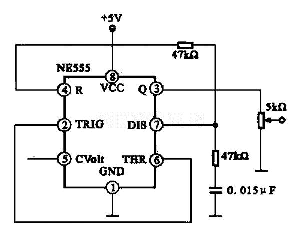
A 1 kHz square wave signal generator is created using a time base circuit with an NE555 timer, combined with a time constant circuit consisting of a 47 kΩ resistor and a 0.15 µF capacitor. The circuit utilizes the...
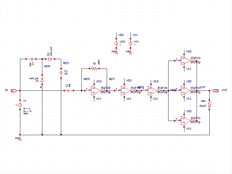
This schematic example demonstrates a sinusoidal voltage input at a frequency of 10 kHz, which is converted to a square wave using an inverter-based circuit. The VDD and VSS rails are connected to +1V and -1V, respectively. The control...
After disappointing results with a transformer-based component tester, there is an interest in generating a ±10 V sine wave at approximately 50 Hz using minimal components. While an ATmega microcontroller could achieve this, it may be considered excessive, requiring...
One unit is in good condition, manufactured in 1979, and is capable of generating sine, triangle, and square waveforms. This unit is retained and utilized as the primary function generator for testing purposes at the main office location. The...
This is a Wien-bridge sine-wave oscillator circuit. This circuit utilizes negative-feedback stabilization to ensure that the gain does not exceed unity. The Wien-bridge oscillator is a type of electronic oscillator that generates sine waves. It consists of an amplifier and...