
Current-monitor
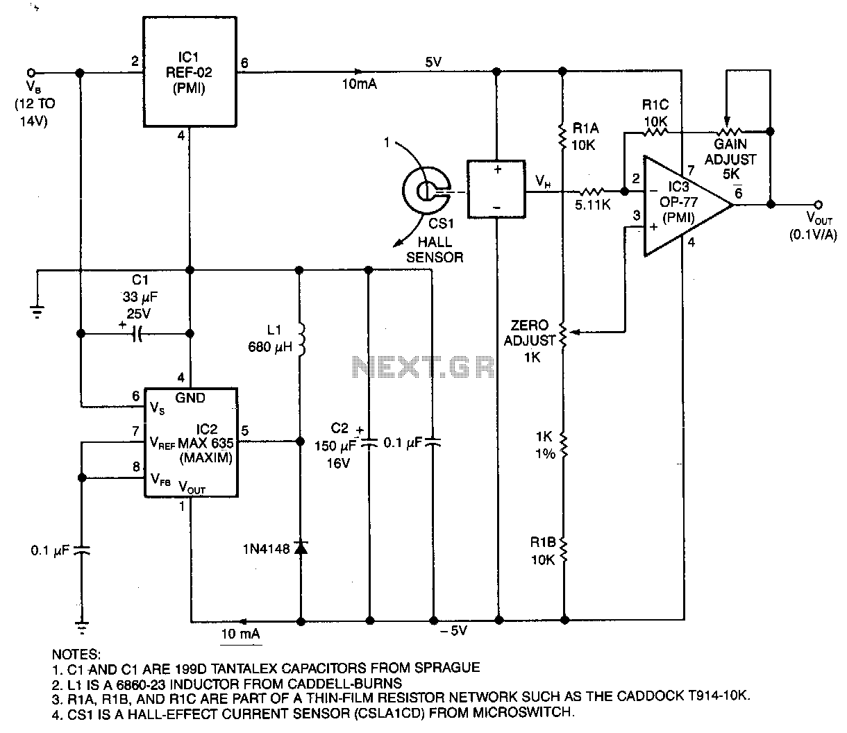
This circuit utilizes a Hall-effect sensor, comprised of an integrated circuit (IC) positioned within a small gap of a flux-collector toroid, to measure current in the range of 0 to 40 A. The current-carrying wire is threaded through the toroid, and the Hall voltage (VH) generated is linearly proportional to the current (I). The current drain from the voltage supply (VB) is less than 30 mA. To monitor the output current of an automobile alternator, for instance, the car battery can be connected between the circuit's VB terminal and ground, with one turn of wire wrapped through the toroid. Alternatively, if space permits, ten turns can be wrapped to measure up to 1 A full scale. When the current (I) is 0 A, the output voltage (VH) of the current sensor (CS) is equal to half of its 10 V bias voltage. The regulators IC1 and IC2 provide a bipolar bias voltage, ensuring that the output voltage (VOUT) is zero when I is zero. This allows for adjustment of the output gain and offset to scale VOUT to 1 V per 10 A.
The Hall-effect sensor circuit operates based on the principle that a magnetic field is generated around a current-carrying conductor. When the wire is threaded through the toroidal core, the magnetic field produced by the current induces a Hall voltage across the sensor. This voltage is directly proportional to the current flowing through the wire, enabling accurate current measurement.
The circuit design includes components such as the Hall-effect sensor IC, which is sensitive to the magnetic field changes, and the toroidal core that enhances the magnetic field's strength. The output from the Hall sensor is processed through operational amplifiers (IC1 and IC2), which serve as regulators to create a bipolar output voltage. This bipolar configuration is crucial for centering the output voltage around zero, thus allowing for both positive and negative current measurements.
The adjustment of output gain and offset is facilitated through potentiometers connected to the operational amplifiers. This flexibility enables calibration of the circuit to ensure that the output voltage accurately reflects the measured current. For instance, if the goal is to output 1 V for every 10 A of current, the gain can be set accordingly.
In applications such as monitoring an automobile alternator's output, the circuit can be easily integrated by connecting the battery and wrapping the wire through the toroid. By adjusting the number of turns, the circuit can be tailored for different current ranges, enhancing its versatility for various applications in current sensing and monitoring.This circuit uses a Hall-effect sensor, consisting of an IC that resides in a small gap in a flux-collector torrid, to measure de current in the range of 0 to 40 A. You wrap the current-carrying wire through the toroid; the Hall voltage VH is then linearly proportional to current I.
The current drain from VB is less than 30mA. To monitor an automobile alternator"s output current, for example, connect the car battery between the circuit"s VB terminal and ground, and wrap one turn of wire through the toroid. Or, you could wrap 10 turns-if they fit-to measure 1 A full scale. When I~ 0 V current sensor CS/s VH output equals one-half of its 10 V bias voltage. Because regulators !C1 and IC2 provide a bipolar bias voltage, Vy and VoUT are zero when I is zero; you can then adjust the output gain and offset to scale VoUT at 1 V per 10 A.
🔗 External reference
Related Circuits
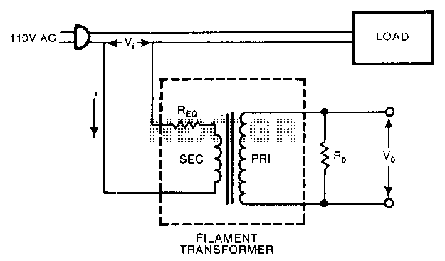
A low-cost filament transformer provides a linear indication of the load current in an AC line. This method causes a slight series voltage drop over a wide range of load currents. A low-cost filament transformer is utilized in applications requiring...
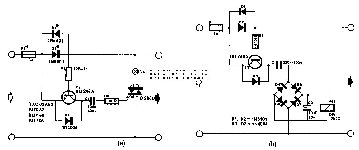
The circuit in Fig. 56-lla activates a signal lamp when it detects a line current consumption exceeding 5 mA and can handle currents of several amperes using suitable diodes in the D1 and D2 positions. Transistor T1 is activated...