
Acoustic Doppler Motion Detector

The described circuit involves a high-frequency audio signal operating within the range of 15 to 25 kHz, which is initially generated by component U1. The signal is then routed through a buffer stage represented by Q1, which ensures that the signal maintains its integrity and strength before being delivered to the speaker (SPKR1).
A portion of this high-frequency signal is directed to a balanced mixer (U2), which plays a crucial role in processing the audio signals. The circuit also incorporates SPKR2, which functions as a microphone to capture ambient audio. This captured audio is subsequently amplified by transistor Q2 before being fed into the balanced mixer U2.
An important aspect of this circuit is its ability to detect the Doppler effect, which occurs when sound waves are reflected off a moving object. This phenomenon results in a shift in the frequency of the reflected sound. The balanced mixer U2 is responsible for producing an output signal that corresponds to the frequency difference between the transmitted and received audio signals.
This output is then coupled through capacitor C16, which serves to block any DC component while allowing the AC signal to pass, and is adjusted by a gain control resistor R23. The adjusted signal is then sent to an amplifier stage (U3), where it is amplified further. The final output is delivered to a third speaker (SPKR3), where the beat note, representing the frequency difference induced by the Doppler effect, can be heard.
This circuit effectively demonstrates the principles of audio signal processing, frequency mixing, and the practical application of the Doppler effect, making it suitable for various audio and detection applications. A high-frequency audio signal (15 to 25 kHz) generated by Ul is fed to buffer Ql and SPKR1. A portion is f ed to balanced mixer U2. Received audio picked up by SPKR2 (used as a microphone) is amplified by Q2 and fed to U2. When sound is reflected from a moving object, the Doppler effect will cause an apparent shift in frequency. U2 produces a signal equal to the frequency difference. This is coupled via C16 and gain control R23 to amplifier U3, where the beat note is heard in SPKR3.
Related Circuits
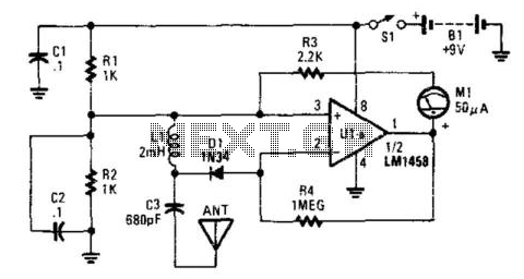
This detector is a half-wave rectifier for RF, which then feeds an operational amplifier. U1A acts as an amplifier, driving meter M1. This circuit can detect milliwatt RF levels from below the AM broadcast band to well above the...
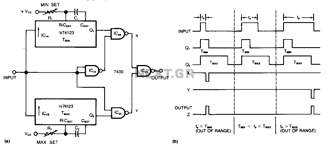
This circuit requires only two integrated circuits (ICs) to monitor a train of positive pulses and produces a single positive output pulse for each input pulse that falls outside specified duration limits. The minimum and maximum limits can be...
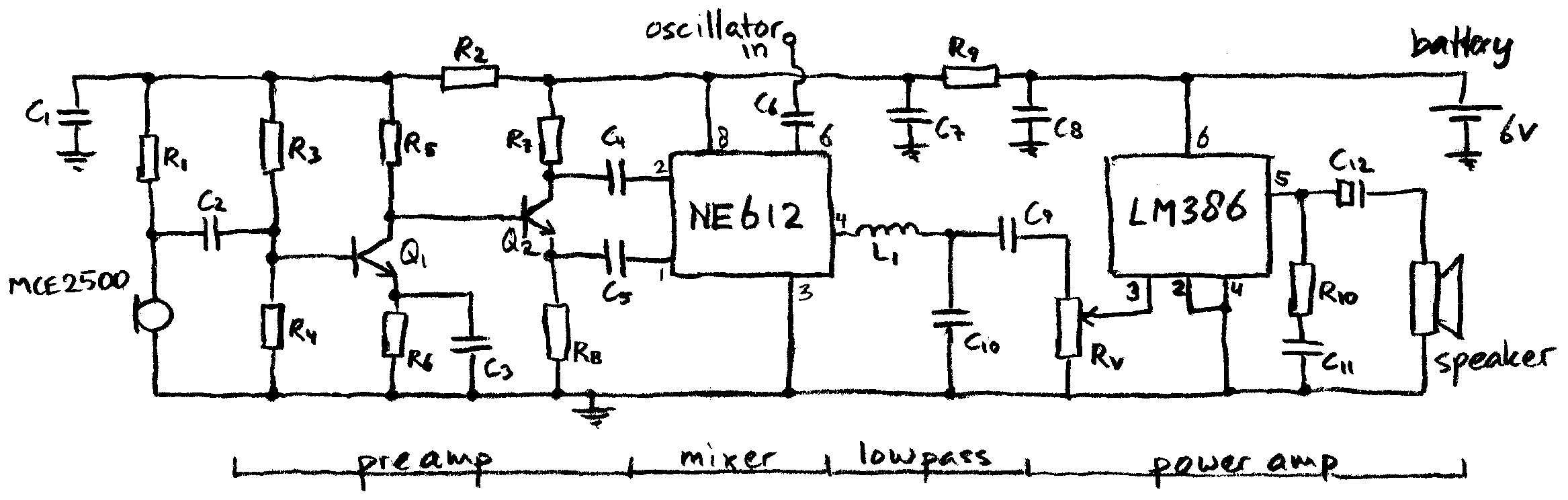
This schematic represents a simple direct-conversion heterodyne detector with a tuning range of approximately 10 kHz to 120 kHz, optimized for use with an electret microphone. The circuit operates with a low current consumption of only 8 mA, allowing...
The ICM7226 is a fully integrated Universal Counter and LED Display driver. It combines a high-frequency oscillator, a decade timebase counter, an 8-decade data counter and latches, a 7-segment decoder, digit multiplexer, and segment and digit drivers, which can...
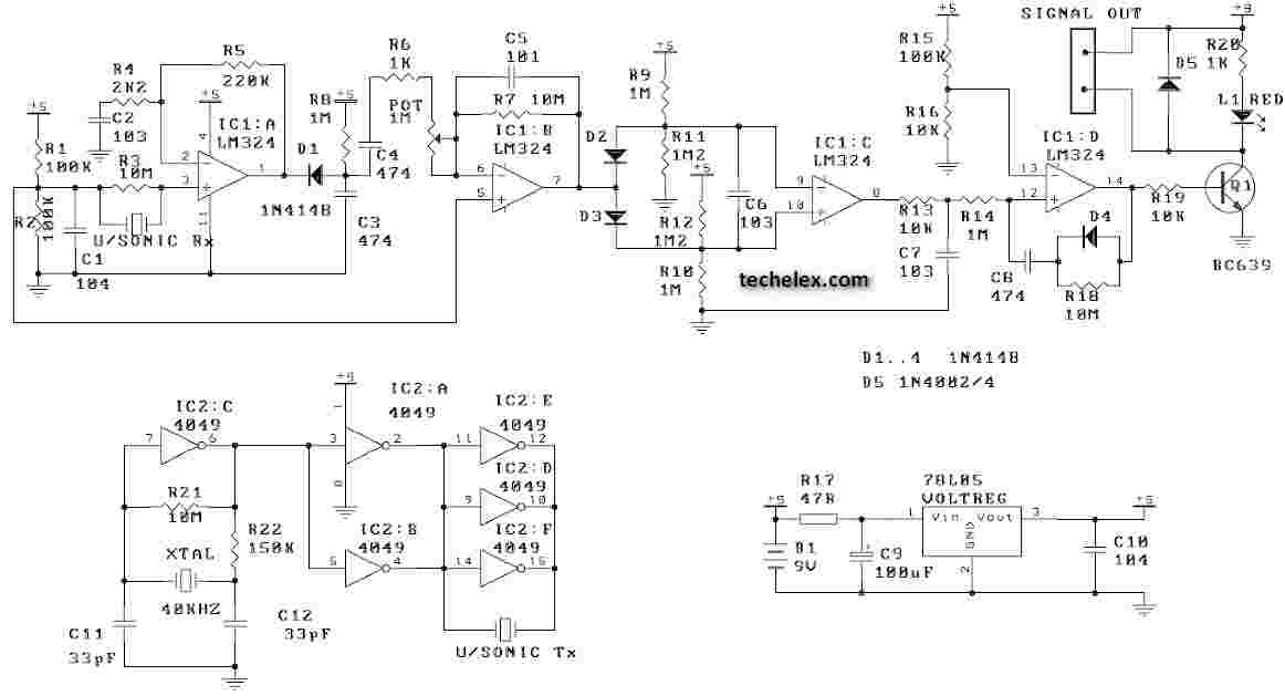
This ultrasonic movement detector circuit utilizes a crystal-locked circuit to achieve maximum performance from the ultrasonic transmitter. The detection circuit is designed to be more sensitive. It is advisable to verify all components against the parts list. Generally, it...
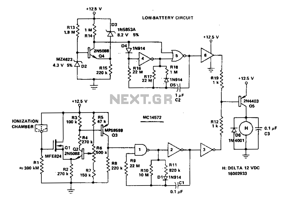
A battery-operated ionization chamber smoke detector features a circuit designed to generate a distinct alarm when the battery approaches the end of its useful life. The circuit employs the MCMOS MC14572 integrated circuit for two alarm oscillators, one for...