


Simple Soil Moisture Meter with 741
#soil moisture
#741 op-amp
#dual power supply
#meter deflection
#plant monitoring
#adjustable resistor
#9V batteries
#sensor probe
#moisture detection
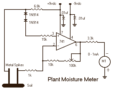
Description: Stick the metal probes into a freshly watered plant and adjust R5 for a mid-scale meter deflection. The meter will monitor the soil wetness and the meter will indicate whether it is too moist or too dry. This circuit uses a dual power supply which could be created by two 9-volt batteries.
The described circuit functions as a soil moisture sensor, utilizing metal probes that are inserted into the soil of a plant. The probes act as conductive sensors that measure the resistance of the soil, which varies with moisture content. When the soil is adequately watered, the resistance decreases, allowing more current to flow through the circuit, which can be detected by the attached meter.
The circuit is powered by a dual power supply configuration, achieved by using two 9-volt batteries. This arrangement not only provides sufficient voltage for the circuit operation but also allows for a positive and negative voltage rail, which can be beneficial for certain components such as operational amplifiers or analog meters that require a bipolar supply.
The adjustable resistor R5 is crucial for calibrating the meter's response. By turning R5, the user can set the meter to indicate a mid-scale deflection, which serves as a reference point for determining the moisture level. If the meter reads above this point, it indicates that the soil is too moist, while readings below suggest that the soil is too dry.
The circuit may include additional components such as a potentiometer for fine-tuning the sensitivity and possibly a diode to protect against reverse polarity connections. A visual indicator, such as an LED, could also be integrated to provide a quick visual reference of the soil moisture status.
Overall, this simple yet effective soil moisture monitoring circuit allows for real-time feedback on the hydration needs of plants, aiding in their care and maintenance.Stick the metal probes into a freshly watered plant and adjust R5 for a mid-scale meter deflection. The meter will monitor the soil wetness and the meter will indicate whether it is to moist or to dry. This circuit uses a dual power supply which could be created by two 9 volt batteries.
The described circuit functions as a soil moisture sensor, utilizing metal probes that are inserted into the soil of a plant. The probes act as conductive sensors that measure the resistance of the soil, which varies with moisture content. When the soil is adequately watered, the resistance decreases, allowing more current to flow through the circuit, which can be detected by the attached meter.
The circuit is powered by a dual power supply configuration, achieved by using two 9-volt batteries. This arrangement not only provides sufficient voltage for the circuit operation but also allows for a positive and negative voltage rail, which can be beneficial for certain components such as operational amplifiers or analog meters that require a bipolar supply.
The adjustable resistor R5 is crucial for calibrating the meter's response. By turning R5, the user can set the meter to indicate a mid-scale deflection, which serves as a reference point for determining the moisture level. If the meter reads above this point, it indicates that the soil is too moist, while readings below suggest that the soil is too dry.
The circuit may include additional components such as a potentiometer for fine-tuning the sensitivity and possibly a diode to protect against reverse polarity connections. A visual indicator, such as an LED, could also be integrated to provide a quick visual reference of the soil moisture status.
Overall, this simple yet effective soil moisture monitoring circuit allows for real-time feedback on the hydration needs of plants, aiding in their care and maintenance.Stick the metal probes into a freshly watered plant and adjust R5 for a mid-scale meter deflection. The meter will monitor the soil wetness and the meter will indicate whether it is to moist or to dry. This circuit uses a dual power supply which could be created by two 9 volt batteries.
Connection Testers
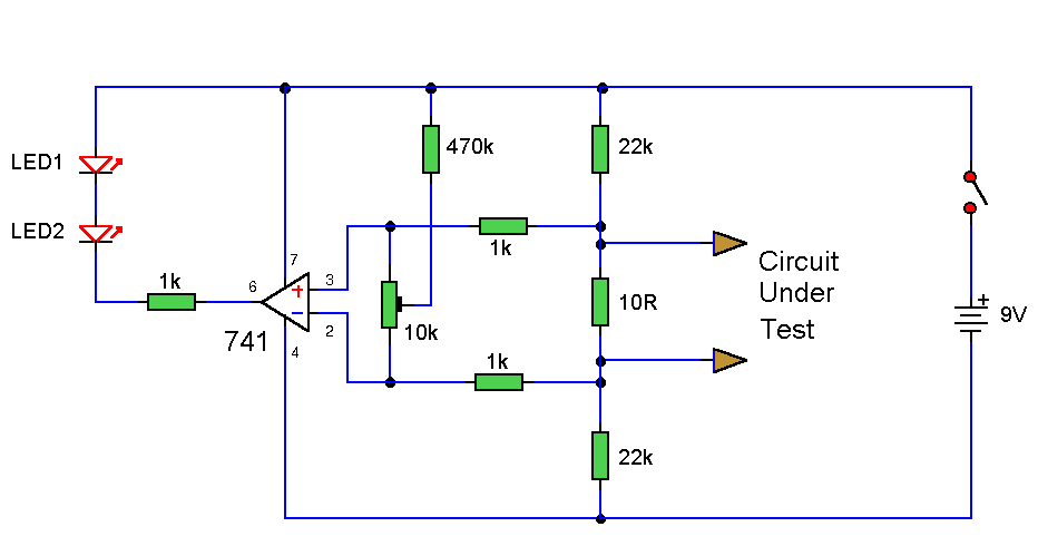
This simple circuit utilizes a 741 operational amplifier (op-amp) in differential mode as a continuity tester. The voltage difference between the non-inverting and inverting inputs is amplified by the op-amp's full open-loop gain. Initially, the 470kΩ and 10kΩ resistors can...
experiments with 741 operational amplifier
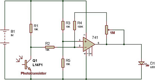
This versatile 741 operational amplifier module can be utilized to create a dark detector using a light-dependent resistor (LDR), a phototransistor, and a photodiode. The amplifier is configured in inverting mode, where it compares the voltage change at pin 2...
dual power supply
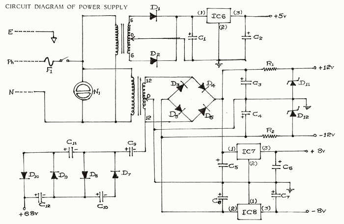
Every electronic device primarily requires a DC power supply for operation. This is a fundamental requirement for any construction project. Consequently, there is a need to obtain multiple voltage values for cost efficiency, convenience, and compact arrangement in various applications....
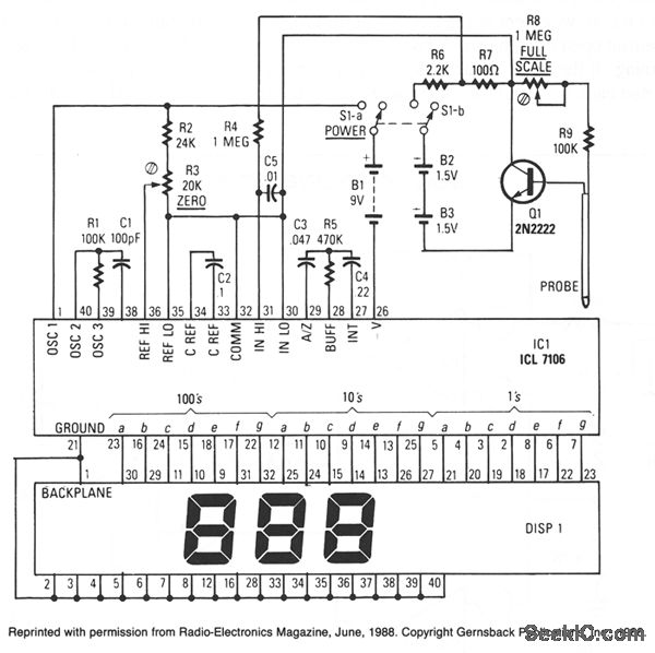
SOIL MOISTURE METER
IC1, an Intersil ICL7106, comprises an A/D converter, a 3.5-digit LCD driver, a clock, a voltage reference, seven-segment decoders, and display drivers. An alternative component, the ICL7107, is suitable for driving seven-segment LEDs. The probe body consists of a five-inch...
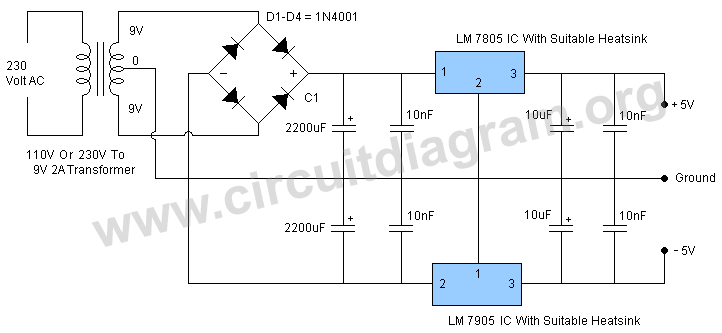
5v dual power supply
The circuit employs a center-tapped transformer that steps down 230V AC or 110V AC to 9V-0-9V. Four 1N4001 diodes are utilized for the rectification of the AC voltage to DC. A 2200μF / 25V electrolytic capacitor is included to filter...
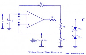
How to make an Astable or Free running Multi vibrator using 741 Op-Amp
Non-sinusoidal waveform generators are also referred to as relaxation oscillators. The op-amp relaxation oscillator described is a square wave generator. Generally, square waves are relatively simple to produce. Similar to the UJT relaxation oscillator, the frequency of oscillation in this...
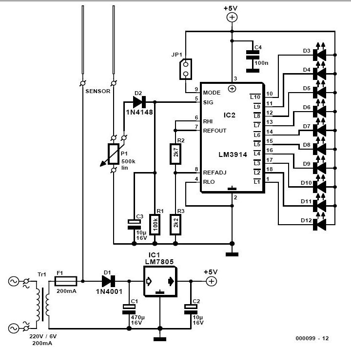
Soil Moisture Tester Circuit
For individuals who prefer not to engage directly with soil, this simple soil moisture tester efficiently assesses the condition of their plants and the level of care they require.
The soil moisture tester is a device designed to measure the moisture...
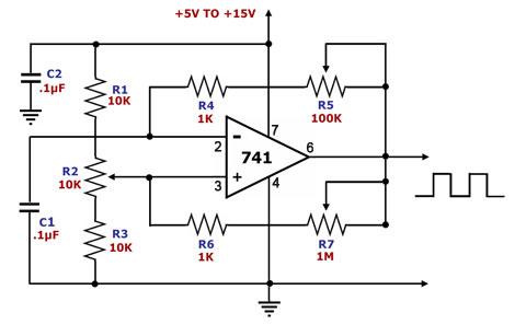
op amp square wave generator
This is a square wave generator circuit. The primary component of this circuit is the 741, a general-purpose operational amplifier. The circuit operates with a single power supply voltage (Vs) that can vary between +5V and +15V. The square wave...
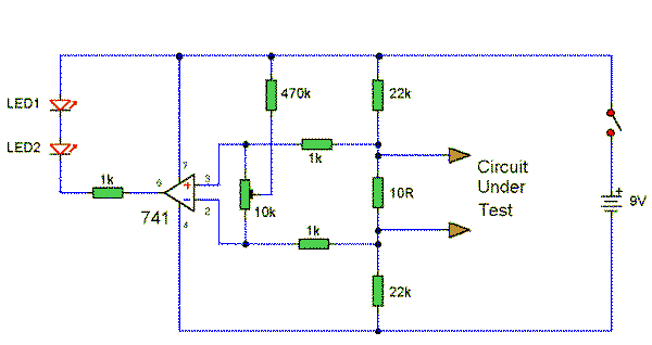
Connection Tester
This simple circuit utilizes a 741 operational amplifier (op-amp) in differential mode to function as a continuity tester. The voltage difference between the non-inverting and inverting inputs is amplified by the op-amp's full open-loop gain. Initially, if the resistors were...