Sensitive-rf-voltmeter

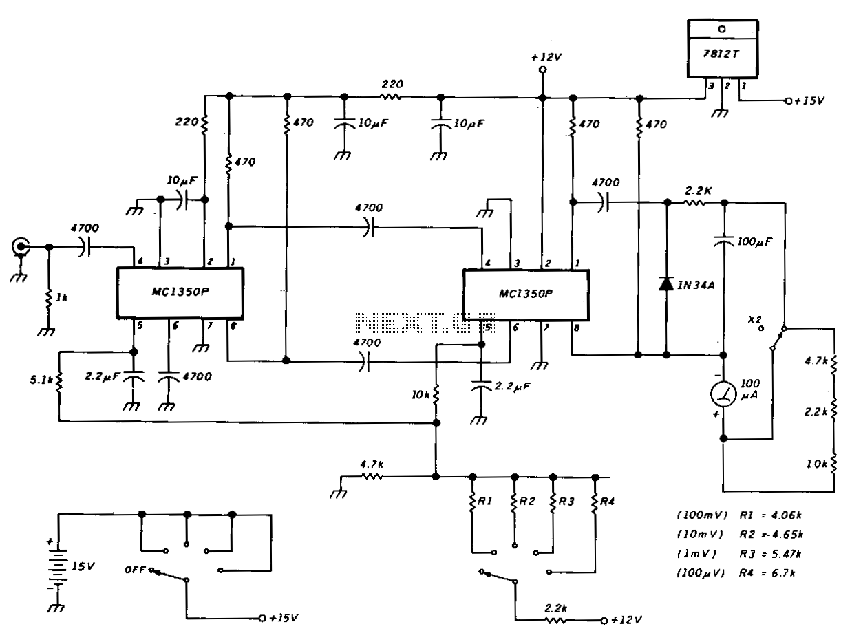
This schematic illustrates a peak-reading diode voltmeter that utilizes two stages of amplification. A 100 µF capacitor is employed to provide a sufficiently large time constant, ensuring adequate meter damping. The limited differential output voltage, combined with an overdamped meter, minimizes needle pinning when an incorrect range is selected or other errors occur. An SPST toggle switch is used to select additional series resistance. This X2 function offers increased overlap of the sensitivity ranges. The resistance values indicated are appropriate for use with a 100 µA meter featuring a 1500 Ω internal resistance.
The peak-reading diode voltmeter is designed to measure the maximum voltage level of a signal, making it particularly useful for applications where transient voltages need to be captured accurately. The two-stage amplification process enhances the sensitivity and accuracy of the measurement, allowing for a more precise reading of the peak voltage.
The 100 µF capacitor plays a crucial role in the circuit by providing a time constant that balances the response time of the meter with the need for stable readings. This capacitor, in conjunction with the amplifier stages, ensures that the meter needle settles quickly without excessive overshoot or oscillation, thus preventing erratic readings.
The limited differential output voltage is a design feature that protects the meter from damage and enhances usability. By preventing excessive deflection of the needle, the circuit reduces the likelihood of needle pinning, which can occur if the user inadvertently selects a voltage range that is too low for the input signal. This design consideration is particularly important in practical applications where user error is a possibility.
The inclusion of an SPST toggle switch to select additional series resistance allows users to adjust the sensitivity of the voltmeter, accommodating a wider range of input signals. This feature is particularly beneficial when measuring varying signal amplitudes, as it provides flexibility in adapting to different measurement scenarios.
The X2 function mentioned in the schematic enables overlapping sensitivity ranges, allowing the voltmeter to effectively handle a broader spectrum of input voltages. This is achieved by adjusting the resistance values, which are specifically chosen for compatibility with a 100 µA meter that has an internal resistance of 1500 Ω. This careful selection of component values ensures optimal performance and accuracy across different measurement conditions.
Overall, this peak-reading diode voltmeter circuit design exemplifies a robust approach to voltage measurement, integrating features that enhance performance while minimizing user error.This schematic shows a peak-reading diode voltmeter driven by two stages of amplification. A 100-ILF capacitor provides a fairly large time constant, which results in satisfactory meter damping. The limited differential output voltage coupled with an overdamped meter prevents most needle pinning when you select an incorrect range position, or make other errors.
An SPST toggle switch selects additional series resistance. This X2 function gives some more overlap of the sensitivity ranges. The resistance values shown are correct for use with a 100-!LA meter with 1500-0 internal resistance.