
servo motor

A servo motor operates on the principle of closed-loop control, allowing for precise position, speed, and torque control. The integrated circuit within the servo processes input signals received through the signal wire, which determines the desired position of the output shaft. The potentiometer provides feedback to the integrated circuit regarding the current position of the shaft, enabling the system to make necessary adjustments to reach the target position accurately.
The gear train amplifies the torque produced by the DC motor, allowing the servo to handle heavier loads with greater efficiency. This assembly is typically housed in a robust casing to protect the internal components and ensure reliable operation in various applications.
Servo motors are widely used in robotics, automation, and control systems where precise movement is essential. They can be classified into different types, such as positional rotation servos, continuous rotation servos, and linear servos, each serving distinct applications based on their operational characteristics.
In terms of electrical connections, the power wire is typically connected to a positive voltage supply, the ground wire to the system ground, and the signal wire to a controller or microcontroller that sends pulse-width modulation (PWM) signals. The duration of the pulse dictates the angle of rotation, allowing for fine control over the servo's movement.
Overall, the servo motor's design and functionality make it an indispensable component in modern electronic systems requiring accurate motion control.So what is a Servo Motor?? A Servo is a small device that incorporates a three wire DC motor, a gear train, a potentiometer, an integrated circuit, and an output shaft bearing. Of the three wires that stick out from the motor casing, one is for power, one is for ground, and one is a..
🔗 External reference
Related Circuits
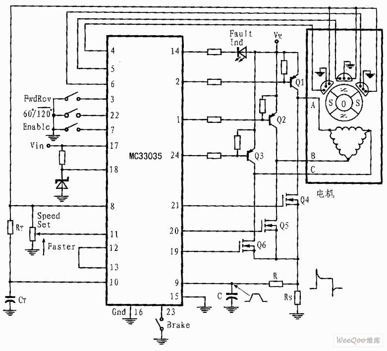
The presented three-phase application circuit features a motor controller circuit connection diagram that operates using a full-wave six-step method. The power switch is a Darlington PNP type, while the lower power switch is an N-channel power MOSFET. Each device...
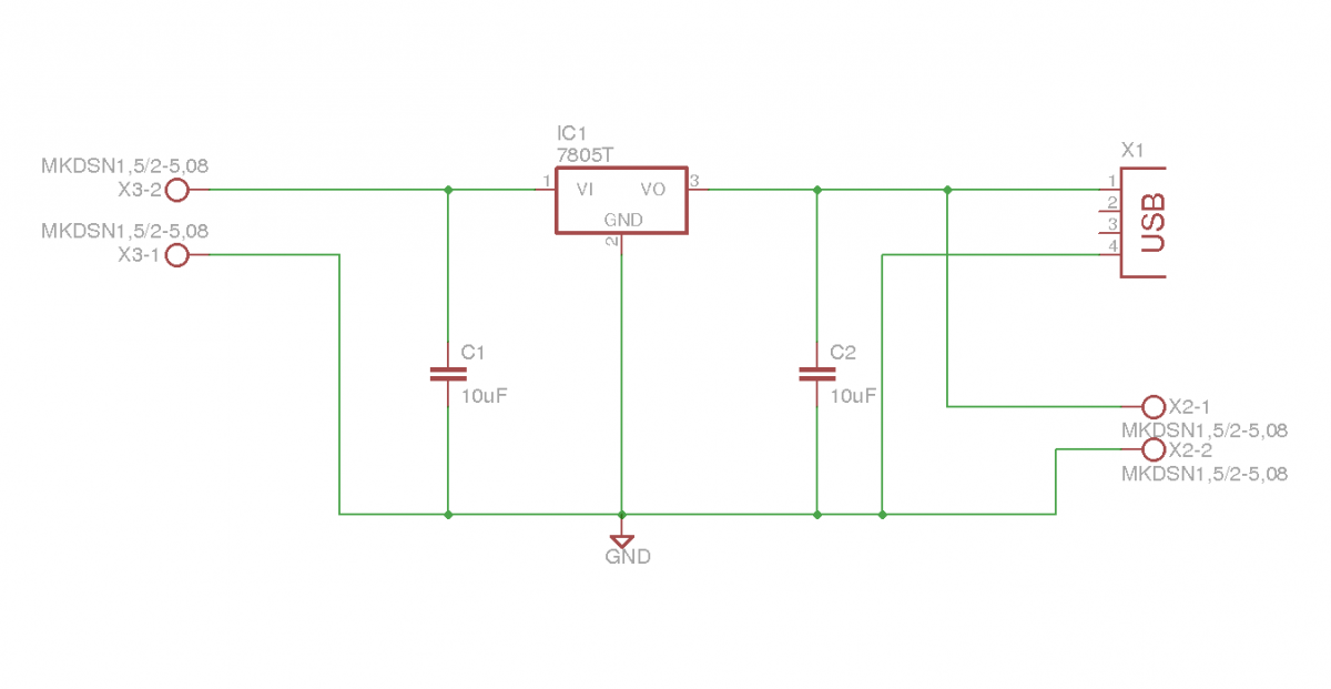
This document outlines the details of several circuits designed and built for a robot. The first circuit is a voltage regulator intended to supply power to a Raspberry Pi from a 7.2V battery. While the circuit is relatively simple,...

If the control circuit of this motor driver is based on a microcontroller or digital component, it is advisable to implement a buffer for each port that controls the stepper motor driver. This precaution helps prevent overloading the microcontroller...
The electronic motor speed controller circuit includes a wireless remote control transmitter circuit and a wireless remote control receiver circuit, as illustrated in the accompanying chart. The wireless remote control transmitter circuit comprises a micro-power wireless remote control transmitter...
Motor control, energy efficiency of inverter (AC drive) selection, and parameters setting guidance in the mining industry: vector control, open loop or closed loop control, with energy braking unit or energy feedback unit. In the context of motor control for...
This type of design can generate a very high amperage current for a fraction of a second, which can be utilized for various applications if properly harnessed. The switching device could be a rotating spark gap, as utilized by...