
Servo Tester Using A 4538

The servo tester circuit utilizing the 4538 integrated circuit is designed to facilitate precise control of servo motors by generating adjustable pulse-width modulation signals. The 4538 IC, being a dual astable multivibrator, allows for the generation of two distinct pulse signals that can be synchronized for effective servo control. The configuration of resistors R1 and the variable potentiometer P1, along with the timing capacitor C1, determines the output pulse width, which is essential for controlling the angle of the servo.
To ensure stability and reliability in operation, it is advisable to use high-quality components, particularly for the timing capacitor C1, as its value directly influences the pulse timing. The circuit requires a stable power supply, typically within the range of 5 to 15 volts, to ensure consistent performance across different servo types.
The output from the servo tester can be connected directly to the control input of standard servos, which interpret the pulse width as position commands. This feature makes the tester invaluable for both testing and calibrating servos, allowing users to determine the exact pulse width required for specific positions.
In practical applications, the servo tester can be used in various fields, including robotics, automation, and remote-controlled vehicles, where precise servo control is crucial. The ability to adjust the pulse width easily enables users to fine-tune servo responses, ensuring optimal performance in their respective applications.Everybody who regularly works with servos will know several instances when such a servo tester will come in handy. The function of a servo tester is to generate a pulsing signal where the width of the positive pulse can be varied between 1 and 2 ms.
This pulse-width determines the position the servo should move to. The signal has to repeat itself continuously, with a frequency of about 40 to 60 Hz. These circuits often use an NE555 or one of its derivatives to generate the pulses. This time we have used a 4538 for variety. This IC contains two astable multi-vibrators. You can see from the circuit diagram that not many other components are required besides the 4538. The astable multi-vibrator in a 4538 can be started in two ways. When input I 0 (pin 5 or 11) is high, a rising edge on input I 1 (pin 4 or 12) is the start signal to generate a pulse. The pulse-width at the output of IC1a is equal to (R1+P1)G—C1. This means that when potentiometer P1 is turned to its minimum resistance, the pulse-width will be 10 k G— 100 n = 1 ms.
When P1 is set to maximum (10 k), the pulse-width becomes 20 k G— 100 n = 2 ms. At the end of this pulse inverting output Q generates a rising edge. This edge triggers IC1. B, which then generates a pulse. The pulse-width here is 82 k G— 220 n 18 ms. At the end of this pulse the Q output will also generate a rising edge. This in turn makes IC1. A generate a pulse again. This completes the circle. Depending on P1, the total period is between 19 and 20 ms. This corresponds to a frequency of about 50 to 53 Hz and is therefore well within the permitted frequency range. 🔗 External reference
Related Circuits
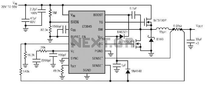
Burst Mode operation maintains high efficiency at light loads by reducing IC quiescent current to 120 µA. Light load efficiency is also improved with the reverse inductor current inhibit function, which supports discontinuous operation. Additional features include an adjustable...
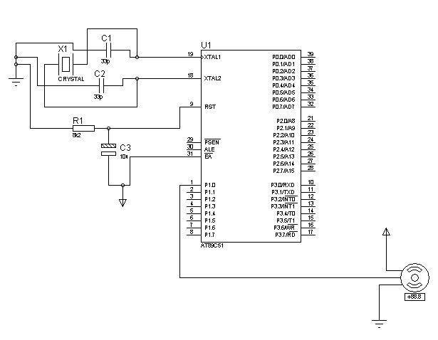
The control signals for the motor's rotation are generated by an 8051 microcontroller. For foundational concepts and information about a servo motor, refer to the article on Servo Motors. The source code utilized is based on the AT89S51 microcontroller....
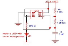
This article offers valuable information for creating a specific oscillator or pulse generator using integrated circuits (ICs), resistors, and capacitors, regardless of the version of the 555 IC utilized. The 555 timer IC is a versatile component widely used in...
A radio remote control system utilizing DTMF (Dual-Tone Multi-Frequency) technology is presented. This circuit allows for the control of various electrical appliances through radio frequency signals. The described radio remote control system employs DTMF tones, which are generated by a...
This compact Infrared Remote Control Tester circuit is designed to verify the functionality of an infrared remote control unit. The circuit operates by connecting a piezo buzzer directly to an IR receiver integrated circuit (IC). The TSOP1738 integrated IR...

Before using LEDs, it is advisable to test them. An LED tester allows for testing even in low light conditions. LEDs are available in various shapes and colors, with some featuring clear, colorless packages and others having colored plastic...