
simple 555 amplifier

The 555 timer IC is a versatile device widely used in various electronic applications, including as a pulse-width modulation (PWM) generator. In this configuration, it can amplify signals by modulating the width of the output pulses based on an input signal. The typical setup involves connecting the 555 timer in astable mode, where it continuously oscillates between high and low states, producing a square wave output.
For this application, the 555 timer is configured with specific resistor and capacitor values to achieve an oscillation frequency of approximately 66 kHz. The frequency is determined by the formula:
\[ f = \frac{1.44}{(R1 + 2R2) \times C1} \]
where \( R1 \) and \( R2 \) are the resistances connected to the discharge and threshold pins, respectively, and \( C1 \) is the timing capacitor. The output from the 555 timer will be a square wave that alternates between high and low states at the specified frequency.
In this scenario, the output frequency is high enough that most audio speakers will not respond directly to the oscillation. Instead, they react to the average DC level of the modulated output signal, effectively demonstrating the principles of pulse-width modulation. This principle allows for control of the power delivered to the speaker without generating audible noise at the modulation frequency.
It is essential to note that during operation, the 555 timer may generate considerable heat, especially when used for extended periods or with insufficient heat dissipation measures. Therefore, it is advisable to limit the usage duration to brief demonstrations to prevent overheating and potential damage to the IC.
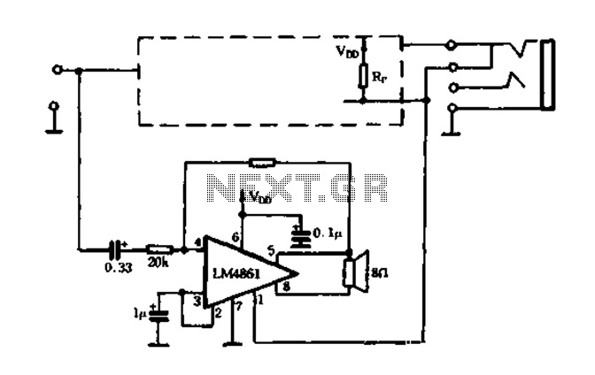
Overall, this application of the 555 timer showcases its ability to perform as an amplifier through pulse-width modulation, providing a practical example of how modulation techniques can control power delivery in electronic circuits.The 555 can be used as an amplifier. It operates very similar to pulse-width modulation. The component values cause the 555 to oscillate at approx 66kHz and the speaker does not respond to this high frequency. Instead it responds to the average CD value of the modulated output and demonstrates the concept of pulse-width modulation.
The chip gets v ery hot and is only for brief demonstrations. 🔗 External reference
Related Circuits
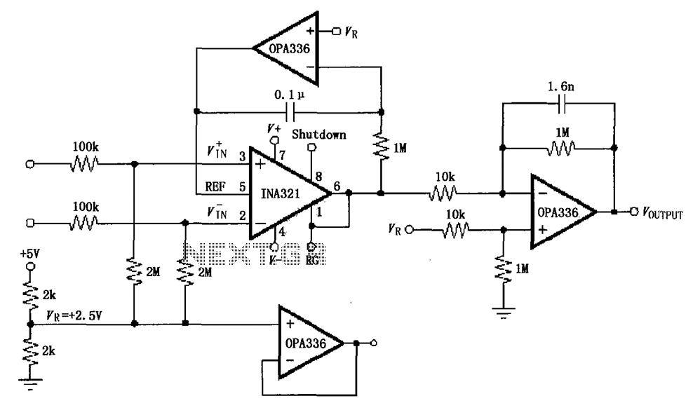
The INA321/322 forms a low-cost, medium-accuracy ECG amplifier circuit. The INA321 receives input signals from the patient's arm, amplifying them before sending the modified output to the operational amplifier OPA336. The OPA336 generates an output voltage from the inverting...
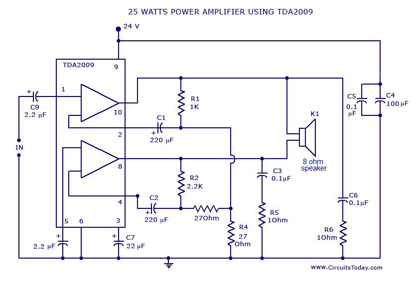
Power amplifier circuit diagram with schematics. This simple audio power amplifier circuit is designed for 25 watts output power using TDA 2009 IC, which has two channels (stereo), 12.5 W for each channel. The described power amplifier circuit utilizes the...
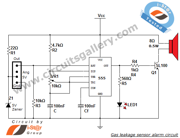
This article discusses a home security alarm circuit designed to detect LPG gas leakage. The circuit utilizes a gas sensor module, SEN 1327, which incorporates a QM 6 gas sensor. The output signal from this gas sensor module is...
This is a very basic circuit for flashing one or more LEDs and also to alternately flash one or more LEDs. It uses a 555 timer setup as an astable multivibrator with a variable frequency. With the preset at...
This diagram originates from the Progressive Communications Receiver featured in most recent ARRL Handbooks. The amplifier is utilized wherever an intermediate frequency (IF) amplifier is necessary. W6BKY has published an article on Hamradio-online that details the construction of this...
The circuit utilizes a MOSFET to automatically shut down the FIG system. When the headset is inserted, the contact opens, causing the MOSFET gate to connect to a high voltage, allowing current to pass. The LM4880 is configured to...