
Simple Battery Level Indicator

The battery level indicator circuit is designed to visually represent the remaining charge in a battery, commonly used in portable devices such as mobile phones. The circuit generally employs a series of LEDs to indicate different levels of battery charge. For example, a common configuration may include three LEDs, which light up in sequence as the battery voltage decreases.
The circuit typically consists of a voltage divider, which scales down the battery voltage to a level suitable for the LEDs. The voltage divider is composed of two resistors, R1 and R2, connected in series across the battery terminals. The junction between the two resistors provides a voltage that varies with the battery's charge level. This voltage is then fed into a comparator or a microcontroller that determines which LED should be turned on based on the voltage level.
The LEDs are connected to the output of the comparator or microcontroller, with each LED representing a specific voltage range. For instance, if the battery voltage is above a certain threshold, the green LED may light up, indicating a full charge. As the voltage drops, the yellow LED might activate to indicate a medium charge level, and finally, the red LED would illuminate when the battery is low.
In addition to the basic components, the circuit may include a potentiometer to calibrate the voltage thresholds for each LED, ensuring accurate representation of the battery level. A resistor in series with each LED is also necessary to limit the current flowing through the LEDs, preventing damage and ensuring longevity.
Overall, this battery level indicator circuit is a straightforward and effective solution for monitoring battery status in various electronic devices, providing users with a clear visual indication of remaining power.Here the circuit diagram of simple and easy made battery level indicator. In general, in mobile phones, the battery levels is displayed in dot or bar style. This helps you to effortlessly acknowledge the battery level. On this page we provi.. 🔗 External reference
Related Circuits
This is the basic interface I used as part of my Computerized Room project. This is the parallel interface only. The 8 bit input card can be found, along with the rest of the project, at Computerize Your Room/House....

This circuit generates sine and square wave signals with frequencies ranging from below 20 Hz to above 20 kHz. The advantage of this circuit diagram is that the output frequency can be adjusted by varying the variable resistor R6. The...
A simple NiCd charger can be constructed using commonly available components and an inexpensive LM317 or 78xx voltage regulator. It incorporates a current limiter made up of resistor R3 and a transistor, allowing it to charge multiple cells until...
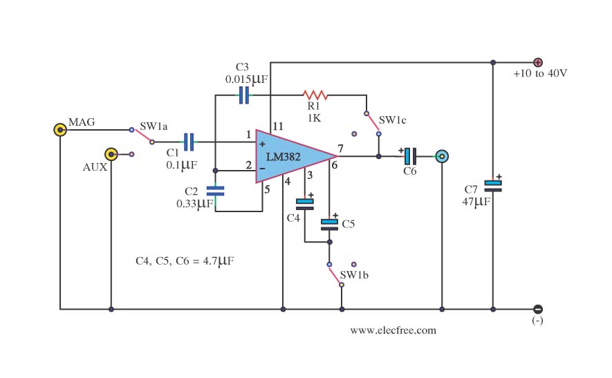
This is a simple preamplifier circuit. It can accept a general AUX sound signal as well as a signal from a microphone. The purpose of the circuit is to amplify the sound signal at the initial stage using an...
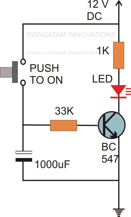
Without the specified delay, the circuit could malfunction or even sustain damage. A capacitor, which is a crucial component of the circuit, is positioned at the other end of the base resistor rather than directly connected to the base...
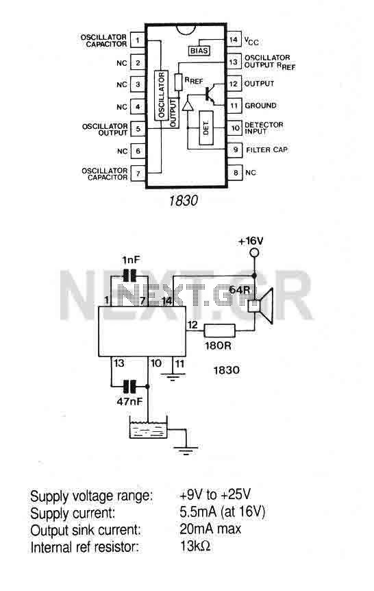
The IC is ideal for detecting the presence, absence or level of water or other conducting liquids. A detector determines the presence or absence of fluid by comparing the resistance of the fluid with the IC's internal reference resistance....