
Simple but reliable car battery tester circuit

The LM3914 is a bar graph/LED dot display driver that can drive up to ten LEDs in a linear or dot mode, making it suitable for visual representation of analog signals. It operates within a voltage range of 3V to 25V, allowing for flexibility in various applications. The LM3914 has a built-in reference voltage that simplifies design requirements, as it eliminates the need for additional components to regulate the input voltage.
In a typical application, the circuit can be configured to measure and display voltage levels, audio signals, or other analog inputs. The configuration involves connecting the input signal to the IC's input pin, which then translates the analog value into a corresponding number of illuminated LEDs. The output can be customized by selecting the appropriate mode of operation—either bar graph or dot mode—by connecting a pin to ground.
The circuit design may also include additional components such as resistors to limit current through the LEDs, ensuring proper brightness and longevity. Capacitors might be added for filtering purposes to stabilize the input signal and reduce noise, enhancing the accuracy of the displayed readings.
This versatility and ease of use make the LM3914 an excellent choice for various electronic projects, including audio level meters, battery level indicators, and other visual signal displays. The simplicity of the design, combined with the IC's built-in features, allows for rapid prototyping and implementation in both educational and professional settings.This circuit uses the popular and easy to find LM3914 IC. This IC is very simple to drive, needs no voltage regulators (it has a built in voltage regulator) and can be powered from almost every source.. 🔗 External reference
Related Circuits
Very little extra circuitry is needed to do both forward and backward walking sequences along with a few other tricks. The PIC16F818 has a lot of features that work well in this situation. As you can see from the...

Rosemary's original test circuit is shown in the article she tried to have published in a refereed scientific journal, but the submission was always rejected. In the last 5 months, I have had extensive email correspondence, and numerous telephone...

The circuit consists of a 5V TOP414G isolated switching power supply with a 2A output. C1 serves as the input filter capacitor. The circuit includes a voltage clamp protection mechanism composed of VD1. The control terminal is connected to...
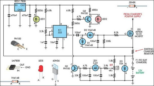
Most off-the-shelf car battery chargers cannot be left connected to the battery for long periods of time as overcharging can cause battery damage. The operation of car battery chargers typically involves converting alternating current (AC) from a wall outlet into...
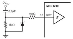
A flash memory schematic can be created using various reset sources, including power-on reset, external reset, software reset, watchdog timer reset, and brownout reset. The accompanying figure illustrates a recommended external reset circuit for the MSC1210, which includes a...
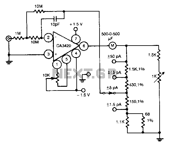
This circuit utilizes the exceptionally low input current of 0.1 pA from the CA3420 BiMOS operational amplifier. It employs a single 10-MΩ resistor. The circuit operates within a range of ±50 pA, achieving a maximum full-scale sensitivity of ±1.5...