
Simple Car Preamplifier and Artificial Earth

The preamplifier circuit described operates with a standard configuration, ensuring that the input signal is AC coupled. This design choice is essential for blocking any DC components that may be present in the input signal, thereby preventing potential distortion or saturation of the amplifier stage. The use of capacitors for AC coupling is a common practice in audio and signal processing applications.
The circuit employs an artificial ground, established by two resistors, R1 and R2. This configuration effectively creates a virtual ground at half the supply voltage, which is typically around 13.8V in automotive applications. This voltage level is optimal for interfacing with a 12V battery system, ensuring compatibility with the vehicle's electrical architecture. By setting the artificial earth at this midpoint voltage, the circuit can maintain proper signal integrity and allow for symmetrical signal handling.
Gain control is facilitated through the adjustment of resistors R105 and R205. By selecting lower resistance values, such as 4.7kΩ, the maximum gain of the preamp can be limited to 3 (equivalent to 10dB). This level of gain is often sufficient for various audio applications, providing a good balance between signal amplification and noise performance. It is important to note that excessive gain can lead to distortion, particularly in environments with significant electrical noise, thus careful consideration of these resistor values is advisable to optimize performance based on the specific application requirements.
Overall, this preamp circuit exemplifies a straightforward yet effective design, suitable for a range of automotive and audio applications, ensuring reliable performance while maintaining simplicity in its configuration.The preamp circuit is completely conventional, and by necessity is AC coupled throughout. The artificial earth is derived by two resistors (R1 and R2), which will set the "earth" at exactly 1/2 the supply voltage. This is nominally 13.8V in all cars, since this is the proper charging voltage for a 12V battery. To reduce the maximum gain, simply reduce the values of R105 and R205. For example, reducing these to 4k7 will provide a maximum gain of 3 (10dB), which in reality is probably enough.
🔗 External reference
Related Circuits
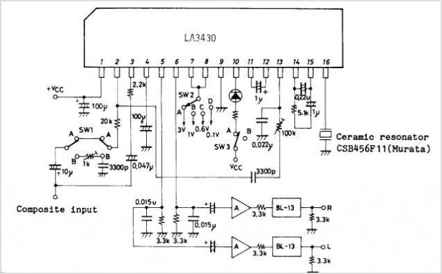
The LA4165M Recording-Playback Integrated Circuit (IC) integrates the necessary functions to design recording and playback systems, as well as motor control circuits, for both micro and standard cassette tape recorders into a single chip. It features automatic audio input...
This battery charger operates by continuously charging at maximum current, gradually tapering off as the battery approaches full voltage. The full load current from the supply transformer and rectifier section is 4.4A. The current decreases to 4A at 13.5V,...
Stick the metal probes into a freshly watered plant and adjust R5 for a mid-scale meter deflection. The meter will monitor the soil wetness and the meter will indicate whether it is too moist or too dry. This circuit...
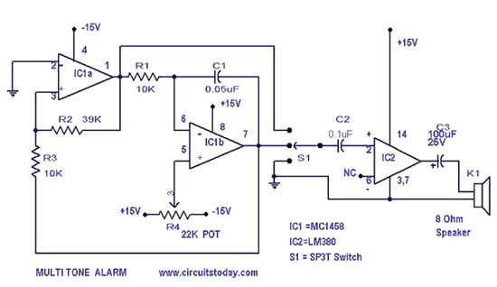
A simple alarm circuit with a diagram and schematic that generates a multi-tone sound. This alarm circuit is suitable for use in burglar alarms and sirens and is designed using dual op-amps MC1458 and LM380. The described alarm circuit utilizes...
In this circuit, the SP6126 is configured as a Zeta converter to supply 0.3A for driving four series-connected LEDs. The SP6126 is a flexible and economical controller that provides the necessary functions required by a Zeta regulator. This report...
The electric car remote control circuit diagram enables the model car to move forward and backward, as well as turn left and right. It is simple and easy to operate. The radio remote control receiver demodulation circuit utilizes TWH9238...