
simple circuit willing to pay for full design!

The circuit in question appears to involve fundamental electronic components, which may include resistors, capacitors, diodes, transistors, and integrated circuits. Each of these components plays a crucial role in the overall functionality of a circuit.
Resistors are used to limit current flow and divide voltages, while capacitors store and release electrical energy, often used for filtering or smoothing signals. Diodes allow current to flow in one direction only, serving as protective elements against reverse polarity. Transistors serve as switches or amplifiers, controlling the flow of current based on input signals. Integrated circuits (ICs) can encapsulate multiple functions into a single package, providing advanced capabilities such as logic processing or signal modulation.
To create a basic electronic schematic, one would typically start by identifying the power source, which could be a battery or a power supply. The components would then be connected using conductive paths, represented by lines on the schematic. It is essential to ensure that the polarity of components such as diodes and electrolytic capacitors is correctly oriented to avoid circuit failure.
The arrangement of components should be logical, following the intended function of the circuit. For example, in a simple LED circuit, a resistor would be placed in series with the LED to limit current, and a power source would be connected to the circuit. The schematic would clearly show the connections, with appropriate labels for each component to facilitate understanding and troubleshooting.
Overall, a well-designed schematic serves as a blueprint for constructing the physical circuit, allowing for effective assembly, testing, and modification as needed.Hi everyone, A bit of background first, I know only the basics of electronics (ie: I know what components do and how to read schematics), but have no.. 🔗 External reference
Related Circuits
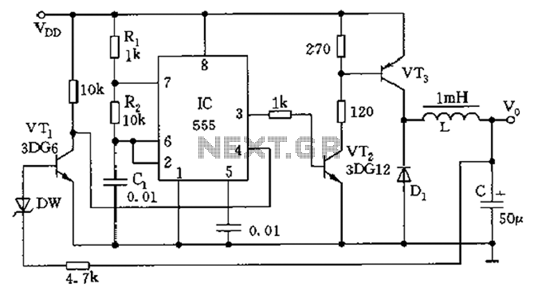
The circuit consists of a 555 timer configured as an astable multivibrator along with resistors R1 and R2 and capacitor C1. It generates an oscillation frequency of approximately 10 kHz with a duty cycle close to 50%. Transistors VT2...
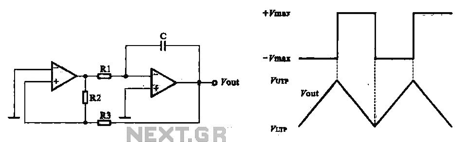
This circuit utilizes two operational amplifiers configured as triangular wave oscillators. It demonstrates a practical application of a relaxation oscillator that employs a voltage comparator to execute the switching function. The schematic in FIG. 2 illustrates the composition of...
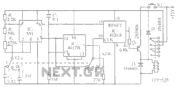
The system operates between 10 minutes to 2 hours, featuring a 100-line bell controlled by a multi-gear stick labeled S2 41f. The integrated circuit (IC) functions as a self-excited multivibrator. The device can manage binary pulses ranging from 3...
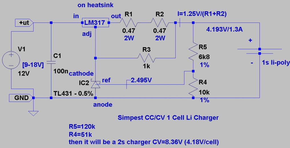
This is a Lithium-ion charger for LiPo batteries. The circuit schematic illustrates the configuration for charging a single 3.7V LiPo battery, but the voltage can be adjusted to charge multiple batteries in series. The LiPo charger establishes a current...
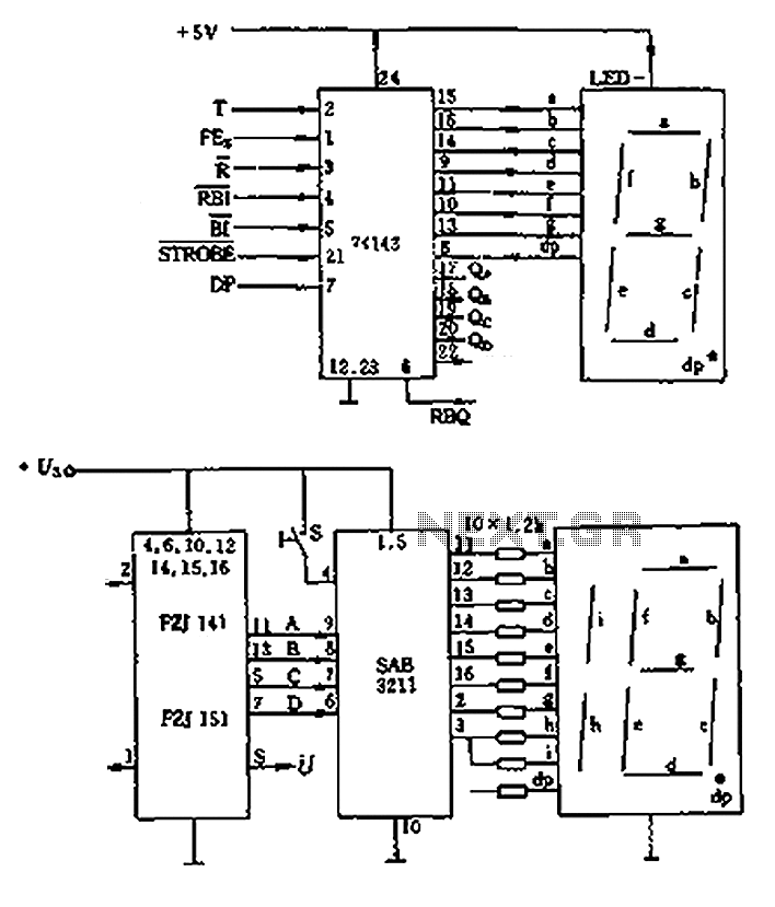
The decimal seven-segment storage decoding drive unit 74HC143 provides a constant output for all segments, each at a voltage of 5V and a current ranging from approximately 15mA to 22mA. The BCD data for the seven-segment decoder can be...
This document presents plans for a simple ground plane antenna that is effective in the FM band (88-108 MHz). It is constructed from a small plastic disk. The 6 x 6 loop antenna, designed by Graham Maynard, is highlighted...