
SIMPLE DOOR ALARM CIRCUIT

The simple doorbell circuit typically consists of a few essential components: a power source, a switch, a bell or chime, and connecting wires. The power source can be a standard AC or DC supply, depending on the specifications of the bell used. The switch serves as the triggering mechanism, which, when pressed, completes the circuit and activates the bell.
In this design, the switch is positioned outside the home or room, allowing visitors to ring the doorbell easily. When the switch is pressed, current flows from the power source through the switch to the bell. The bell will then produce a sound, alerting the occupants of the home to the presence of a visitor.
To ensure safety and functionality, it is important to use components that can handle the voltage and current levels of the power source. Additionally, proper insulation and secure connections should be maintained throughout the assembly to prevent any short circuits or electrical hazards.
This doorbell circuit can be further enhanced by integrating features such as LED indicators to show when the doorbell is activated or by using a wireless system to eliminate the need for extensive wiring. The simplicity of this circuit allows for easy troubleshooting and modifications, making it a practical choice for basic doorbell applications.Here is the circuit diagram for simple door bell, you can assemble this circuit inside your room or home where as keep the switch outside your home or room that is easily noticable by the visitors. The working of this circuit is almost similar to my previous project. 🔗 External reference
Related Circuits
The LM317T is an adjustable three-terminal positive voltage regulator that can supply over 1.5 amps with an output voltage range of 1.25 to 37 volts. It features built-in current limiting and thermal shutdown, making it highly reliable and resistant...
This document provides a guide on understanding a simple computer system and its operation. It will examine the BASIC programming language and its statements, enabling communication with external circuitry. The document will also explore how to interface electronic circuits...
A long time ago, when telephones were simple and reliable from an electrical standpoint, telecom operators installed surge protection on all telephone lines at risk from storms. Paradoxically, as modern technology has led to the use of delicate and...
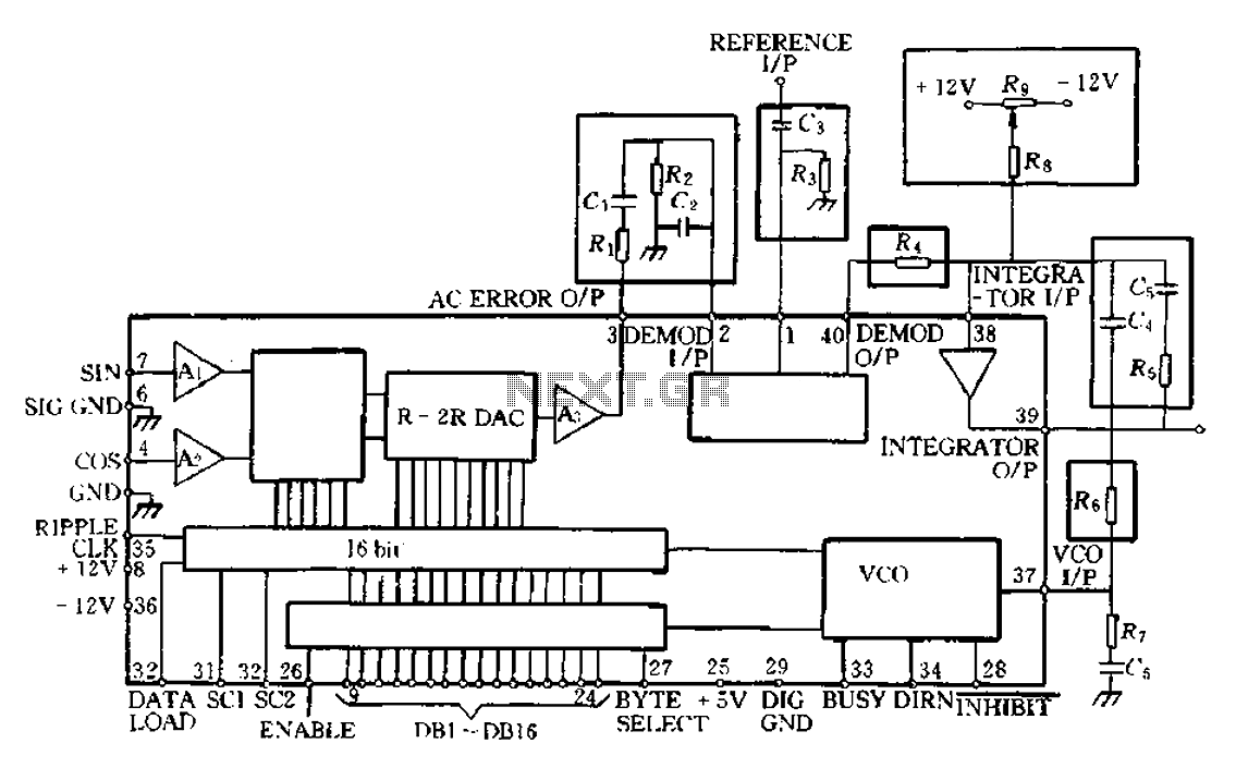
The AD2S80A RDC tracking monolithic integrated circuit is Analog Devices' latest generation RDC. It can be utilized for synchro, resolver, and inductive synchronizer digital conversion. This device integrates advanced CMOS logic and bipolar high-accuracy linear circuits using a BiMOS...

The TDA4863J basic application circuit operates with a positive supply voltage (VP), a flyback power supply voltage (VF), and a negative supply voltage (VN). The input signal is provided from the sawtooth signal input at pins 6 and 7,...
A single-chip metal detector with a detection range of a few inches. This device is useful for identifying nails or screws in walls and floors, as well as locating buried mains cables. The core of the metal detector circuit...