
simple led automatic daynight lamp

The circuit design features a capacitive power supply that operates without a transformer, making it suitable for compact installations in various environments. The use of LEDs significantly enhances energy efficiency compared to traditional lighting solutions, with the option to use white LEDs for improved illumination effectiveness. The inclusion of a 10-ohm resistor serves a critical role in managing voltage transients; this resistor limits the inrush current, thereby safeguarding sensitive components downstream from potential overvoltage conditions.
The MOV acts as a protective element, functioning to absorb voltage spikes and divert excess energy to ground, thus preventing damage to the circuit during transient events. This combination of the 10-ohm resistor and the MOV ensures robust protection against electrical surges, contributing to the longevity and reliability of the device.
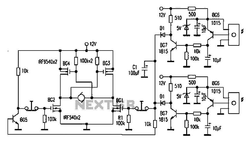
The operational mechanism of the circuit hinges on the light-dependent resistor (LDR), which adjusts its resistance based on ambient light levels. When light intensity decreases, the resistance of the LDR diminishes, leading to an increase in voltage across the variable resistor connected to the comparator transistor. Once this voltage reaches a critical saturation point, the transistor activates, allowing current to flow and turning on the LED. This automatic switching mechanism provides convenience and energy savings, as the lamp only operates when needed, responding dynamically to changes in environmental lighting conditions.
Overall, this circuit exemplifies an efficient, compact design that leverages modern components to achieve effective automatic lighting control.The power supply used here is a capacitive type, thus no transformer is incorporated making the circuit very compact and fixable in any small corner of the particular premise. The use of LEDs in place of a filament bulb makes the application very powereconomicand efficient. The proposed LED automatic day night lamp switch circuit diagram shows red LED being used, however white LEDs would suit the application better, as that would help illuminate the area better than the red LEDs. The 10 Ohms resistor helps to cancel out the initial surge or the voltage rush that might otherwise be potentially harmful to the further stages of the circuit.
The MOV or the varistor placed after the 10 Ohm resistor emhances the protection feature of the unit and grounds all surges that might sneak in after the 10 Ohm resistor. The first transistor is wired up as a comparator, which compares the potential difference across the variable resistor andconductswhen the voltage across it rises to saturation levels.
Theabove rise in the voltage level takes place when the relevant magnitude of light falls on the LDRsurface. Once the resistance of the LDR falls below the set threshold due to higher ambient light, the transistor conducts.
🔗 External reference
Related Circuits
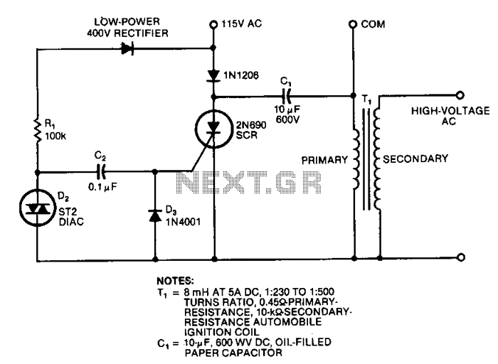
This circuit generates high-voltage pulses using an inexpensive auto ignition coil. By adding a rectifier to the output, the circuit produces high-voltage direct current (DC). The input to the circuit is 115 Vac. During the positive half cycle of...
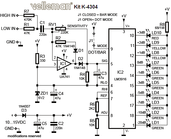
The VU LED indicator is simpler and smaller than its analog counterparts and is commonly used in audio equipment. This version is based on a National Semiconductor integrated circuit (IC) that utilizes a logarithmic response. Each LED operates with...
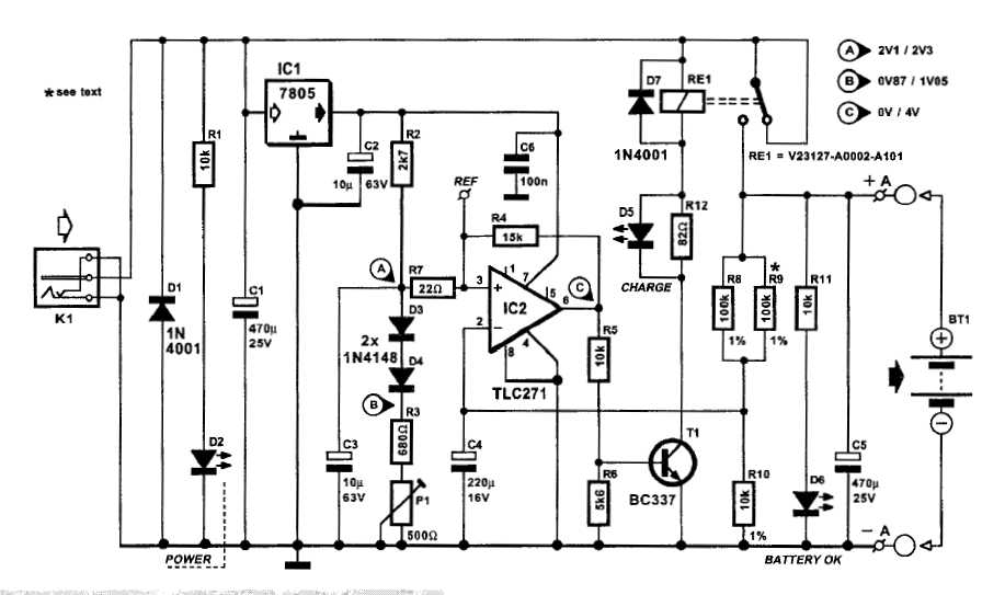
An automatic battery charger initiates the charging process when the battery voltage falls below a specified threshold and ceases charging once the voltage exceeds a predetermined maximum value. The setup is straightforward; simply connect two alligator clips to the...
To explain in a little more detail, using the ATMEGA8's internal 2.5 volt band gap reference means that by using a resistive divider ahead of the A-to-D converter, the input could be scaled such that any voltage range from...
Automatic door control systems typically have a high market price for finished products. The proposed method is suitable for home use, utilizing easily accessible components. This design is ideal for those interested in creating their own automatic door system....
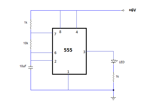
The NE555 is one of the most commonly used timer integrated circuits (ICs). It is a monolithic timing circuit capable of producing accurate and highly stable time delays or oscillations. Similar to general-purpose operational amplifiers, it is reliable, easy...