
Simple logic probe

The circuit described operates as a simple logic level indicator using two transistors and two light-emitting diodes (LEDs). The configuration allows for the visual representation of digital logic states—logic 0 and logic 1—through the illumination of the respective LEDs.
In this circuit, Q1 and Q2 serve as switching elements. When the probe detects a logic 0 (typically represented by a low voltage, close to 0V), Q1 is turned on. This activation allows current to flow through LED D1, causing it to light up. The choice of using an NPN or PNP transistor for Q1 depends on the desired circuit configuration, such as common emitter or common collector setups.
Conversely, when the probe detects a logic 1 (a higher voltage, typically around the supply voltage), Q2 is activated. This allows current to flow through LED D2, illuminating it. Again, either an NPN or PNP transistor can be utilized for Q2, based on the overall design requirements.
D1 and D2 can be selected from a wide range of LEDs, based on color, brightness, and forward voltage specifications. It is important to ensure that the current passing through the LEDs is limited to safe levels, which can be achieved by incorporating current-limiting resistors in series with each LED. The resistor values can be calculated using Ohm's Law, considering the forward voltage drop of the LEDs and the supply voltage.
This circuit can be employed in various applications, such as simple logic testers, educational projects for understanding digital logic, or as visual indicators in more complex electronic systems. The simplicity and versatility of the design make it an effective tool for demonstrating the relationship between digital signals and visual output.If the probe is connected to logic 0, Ql will be turned on lighting Dl. At logic 1, Q2 will be turned on lighting D2. For Ql and Q2 any NPN or PNP transistors will do Similarly, Dl and D2 can be any LEDs.
Related Circuits
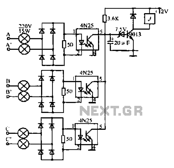
A, B, and C are used for a large power split-phase system. The A + BC range generator phase line features an A-A indole path string containing two 220V/15W bulbs. The bulbs recover based on macro instructions from J...
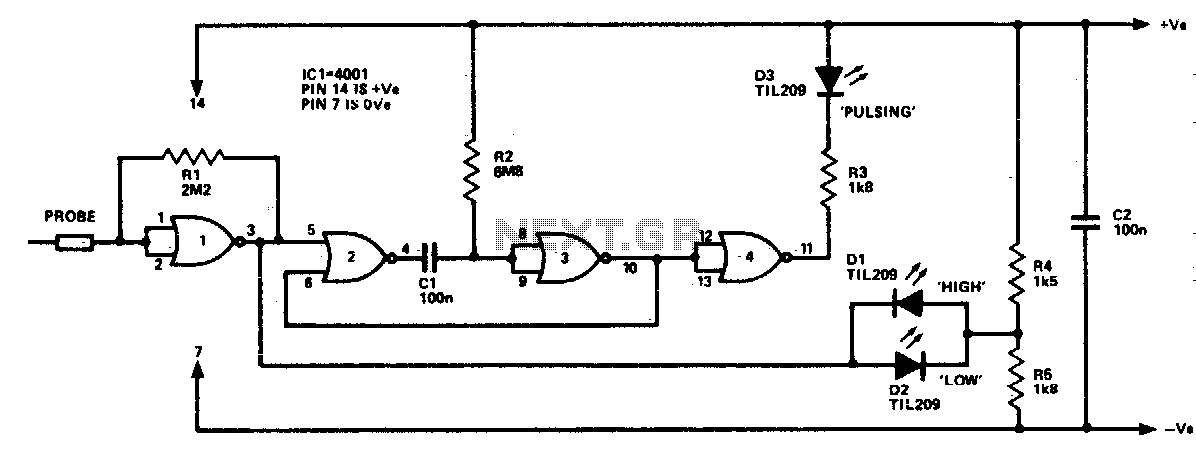
The logic probe can indicate four input states, as follows: floating input - all LEDs off; logic 0 input - D2 switched on (D3 will briefly flash on); logic 1 input - D1 switched on; pulsing input - D3...
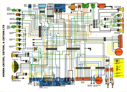
Many inquiries arise regarding motorcycle wiring, particularly among individuals attempting to repair their blinkers or seeking to streamline electronics for custom builds. A crucial aspect of constructing any chopper, bobber, cafe racer, brat bike, or rat rod involves eliminating...
This simple tuned radio frequency receiver was designed and constructed in the mid-1990s. The receiver was tested under urban and field conditions, in varying temperatures. This straightforward circuit exhibits high sensitivity, good sound quality, and reliability. A signal received...
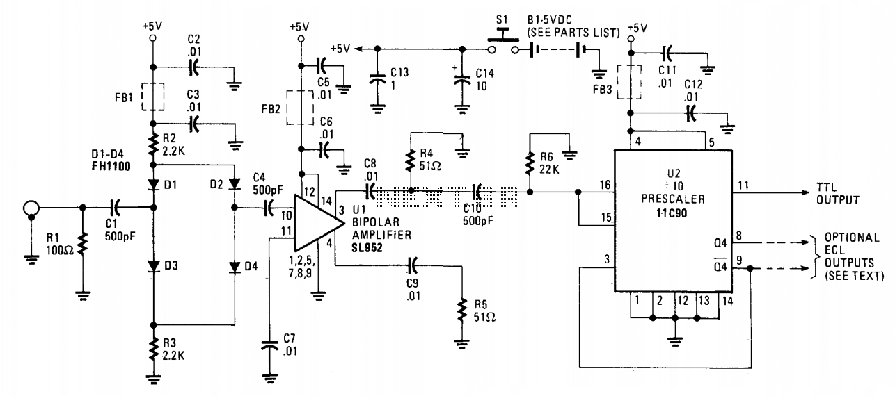
The 650 MHz prescaler probe's input is terminated by resistor R1 and is fed through C1 to the diode limiter composed of diodes D1 through D4. These diodes are forward-biased by the +5 volt supply for small input signals...

This transmitter can be tuned to the FM broadcast band, 2 meters, or other VHF bands by changing C5 and L1. The values provided for C5 and L1 will position the frequency within the FM broadcast band. L1 consists...