
Simple Logic Probe

The logic probe circuit utilizes two NOR gates, configured in a way that allows for effective detection of digital signals. The circuit is powered by a 12V supply, which ensures that both LEDs are normally on when no input signal is detected. This is achieved through the forward biasing of the LEDs, allowing them to illuminate continuously in the absence of input.
When a logic high signal is applied to the probe, the output of the first NOR gate (IC1a) transitions to a low state. This change causes the output of the second NOR gate (IC1b) to transition to a high state. As a result, LED1, which is connected to the output of IC1b, turns off, while LED2, which is connected to the output of IC1a, is activated due to forward biasing. This dual LED indication provides a clear visual representation of the logic state.
In contrast, when a logic low signal is detected at the probe, IC1b's output goes low, resulting in LED1 turning on and LED2 turning off. This mechanism allows the probe to provide accurate feedback on the logic levels present at its input, effectively distinguishing between high and low signals.
The design of this logic probe is particularly beneficial for testing digital circuits, as it can accurately respond to pulse trains, making it a versatile tool for engineers and technicians. The simplicity of the circuit, combined with the clarity of LED indications, enhances its usability in various electronic applications.This simple logic probe has both LEDs on with no signal at the input but due to the nor gates connected to the probe, indicates correctly when a high or low signal is present. It also works correctly for pulse trains. Normally both LEDs are forward biased and therefore on, powered by the 12V supply. When a logic high is present at the probe, IC 1a`s output goes low sending IC1b`s output high. This turns off LED1 but forward-biases (and turns on) LED2. Conversely, a logic low at the probe will send IC1b low, turning LED1 on and LED2 off. 🔗 External reference
Related Circuits
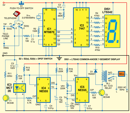
A simple calling bell circuit designed for small offices to summon the office boy using an existing intercom system. The office boy can be called from up to nine locations equipped with extension lines. The system connects to a...
A simple FM transmitter utilizing a single transistor. Mini FM transmitters are commonly regarded as one of the fundamental circuit types for beginners in amateur electronics. When constructed correctly, they offer clear wireless sound transmission via a standard FM...
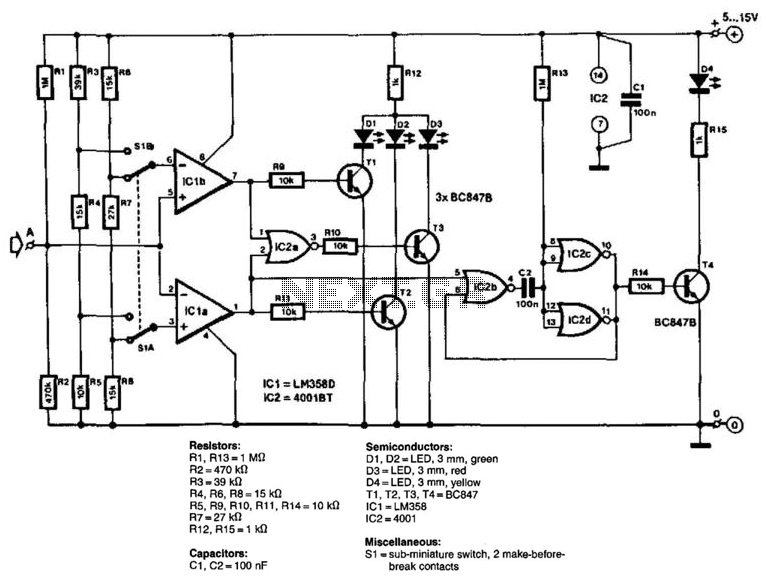
The circuit consists of two comparators that operate with different reference voltages supplied by separate potential dividers. Divider R3/R4/R5 provides a voltage of approximately 40% of the supply voltage (Ucc) to pin 6 of IC1B and about 16% of...
An aerial voltage power supply with a continuously adjustable stabilized output ranging from 0 to 30 VDC. The circuit also incorporates an electronic current limiter that effectively controls the output current from a few milliamperes (2 mA) to a...
The amp was called "El Cheapo 2-30", and was rated at a maximum of 30W per channel into 16 Ohms. It used a single regulated power supply and capacitor coupled speaker. Having a scan of the original, the exact circuit...
Switching Regulator for High Power Efficiency. When it is necessary to convert a high voltage to a significantly lower voltage, a switching regulator is the optimal choice. A switching regulator is an essential component in modern power management systems, particularly...