Simple-low-cost-rf-switch

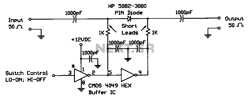
When the digital logic level at the control input is low, the PIN diode is forward-biased by the CMOS gates. The two 1-KΩ bias resistors limit this current to the PIN diode's safe forward current limit. In this state, the switch is on. When the control input is high, the diode is reverse-biased and the switch is off. This switch is well-suited for electronically steered antenna arrays, multipath switching, and other applications requiring small, low-cost RF switches. This particular design was used in a four-pole rotary switch for a Doppler-shift radio direction finder operating at 144 MHz.
The described circuit utilizes a PIN diode and CMOS technology to create a versatile RF switch. In the operational state where the control input is low, the CMOS gates provide a forward bias to the PIN diode. This forward bias allows current to flow through the diode, enabling it to conduct and effectively close the switch. The inclusion of two 1-KΩ bias resistors is crucial, as they limit the current flowing through the diode to ensure it remains within its safe operating limits, thus preventing damage and ensuring reliability.
Conversely, when the control input is set to high, the CMOS gates reverse-bias the PIN diode. This action stops the current flow through the diode, resulting in the switch being in the off state. The rapid switching capabilities of this configuration make it ideal for applications such as electronically steered antenna arrays, where precise control over signal paths is necessary. Additionally, its compact and cost-effective design allows for implementation in various RF applications that require multiple path switching.
The specific application mentioned involves a four-pole rotary switch utilized within a Doppler-shift radio direction finder operating at a frequency of 144 MHz. This application highlights the effectiveness of the PIN diode switch in high-frequency environments, where traditional mechanical switches may introduce unwanted noise or signal degradation. The design ensures that the switching mechanism remains efficient and reliable, contributing to the overall performance of the radio direction-finding system.When the digital logic level at the control input is low, the PIN diode is forward-biased by the CMOS gates. The two 1-KO bias resistors limit this current to the PIN diode"s safe forward current limit. In this state, the switch is on. When the control input is high, the diode is reverse-biased and the switch is ~ott. This switch is well-suited for electronically steered antenna arrays, multiple path switching, and other applications requiring small, low-cost rf switches.
This particular design was used in a four-pole rotary switch for a Doppler-shift radio direction-finder operating at 144 MHz.