
Simple Microphone Mixer

The described mixer circuit is a fundamental audio mixing device intended for use with three dynamic microphones. The design allows for flexibility, enabling the configuration to accommodate a varying number of input channels based on user requirements. The core functionality revolves around level and tone controls, which facilitate the adjustment of audio signals to achieve the desired sound output.
The circuit incorporates resistors R1, R2, and R3, which serve as level controls for each microphone input. By adjusting these resistors, the user can manipulate the gain of each microphone, ensuring that the output levels are balanced and tailored to the acoustic environment. This is particularly important in live sound applications where varying microphone sensitivities can lead to inconsistent audio levels.
Additionally, resistors R9 and R11 are dedicated to tone control, specifically managing bass and treble frequencies, respectively. This allows users to enhance or attenuate specific frequency ranges, contributing to a more refined audio output that can cater to different musical styles or personal preferences.
The mixer operates on a low current draw, making it suitable for battery operation. Utilizing two 9V batteries provides a compact and portable power supply solution, ensuring that the mixer can be used in various settings without the need for bulky power adapters.
To mitigate unwanted noise interference, it is advisable to construct the mixer within a metal enclosure. This not only provides physical protection for the internal components but also acts as a shield against electromagnetic interference, which can adversely affect audio quality. The careful selection of materials and construction techniques will enhance the overall performance and reliability of the mixer, making it a valuable tool for audio professionals and enthusiasts alike.This relatively simple mixer was designed for three dynamic microphones, but can be re-designed for more or less. Level and tone controls are available to tailor the sound to your needs. R1-R3 are level controls. R9 and R11 control bass and treble, respectively. Since the circuit draws such low current, two 9V batteries can be used for a power supply. Building the mixer in a metal case will cut down on noise. 🔗 External reference
Related Circuits
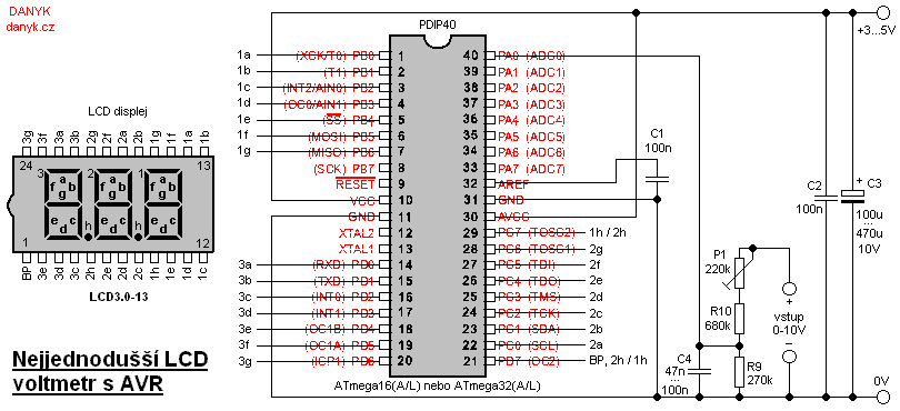
This is likely the simplest digital voltmeter utilizing an Atmel AVR microcontroller and an LCD display. The circuit is managed by a microprocessor IO1 - AVR Atmel ATmega16A, ATmega16L, ATmega16, ATmega32A, or ATmega32. A program is available for free...
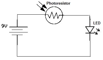
A simple photoresistor circuit will be constructed to demonstrate the operation of a photoresistor, which activates the circuit in the presence of light and deactivates it in darkness. This circuit connects a photoresistor to an LED. When the photoresistor...
This project is a 3 or more lines mixer. For more than 3 inputs you can repeat the input parts (P=10K R=22K). It powered with 9Vdc. The described project is a multi-channel audio mixer designed to handle three or more...
The mixer circuit features three line inputs and three microphone inputs. The microphone inputs are designed to accommodate low impedance dynamic microphones with an impedance range of 200 to 1000 ohms. An electret condenser microphone (ECM) can also be...
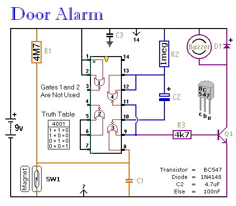
This is a straightforward and easy-to-assemble multi-purpose alarm system. It can be constructed using stripboard or veroboard along with a few inexpensive, readily available components. The alarm is designed to be installed on doors, windows, sheds, garages, cupboards, and...
Even if simple the circuit, plirej' all condition, regarding the distortion and the response of frequency. The resistance of entry is 250K and the load that can drive is between 100R and 2K. The circuit use negative coupling. His...