Simple-mixer

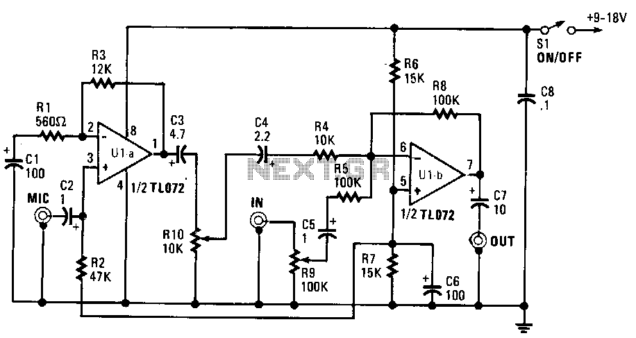
This mixer is constructed using a TL072 dual BiFET operational amplifier featuring a JFET input stage and can be powered by a single-ended power supply ranging from 9 to 18 volts. The microphone input is capacitively coupled to the non-inverting input of U1a. Resistors R1 and R3 establish the voltage gain at approximately 26 dB and function as a negative feedback network for U1a. Capacitors C1 through C3 serve as de-blocking capacitors. Most high-impedance microphones typically output a few millivolts. Additionally, when a preamplifier stage is insufficient, the microphone signal receives an additional boost of around 20 dB within the mixer. The non-inverting input of U1b is biased to half the supply voltage through resistors R6, R7, and capacitor C6. Resistors R5 and R8 form the negative feedback network and set the voltage gain of U1b to unity. Capacitor C5 is utilized for de-blocking at this input.
The described mixer circuit employs the TL072 dual BiFET op-amp, which is known for its low noise and high input impedance, making it particularly suitable for audio applications. The JFET input stage enhances the circuit's ability to handle high-impedance sources such as microphones without significant signal loss. The capacitive coupling of the microphone input ensures that any DC offset is blocked, allowing only the AC audio signal to pass through to the op-amp.
In the first stage, U1a, the configuration of resistors R1 and R3 is critical for achieving the desired gain of 26 dB. This gain is essential for amplifying the weak microphone signal, which typically ranges from a few millivolts. The negative feedback provided by R1 and R3 stabilizes the gain and improves linearity, minimizing distortion in the amplified signal. The de-blocking capacitors C1, C2, and C3 further ensure that any unwanted DC components are filtered out, maintaining the integrity of the audio signal.
The second stage, U1b, is configured to provide additional amplification. The biasing of the non-inverting input to half the supply voltage using resistors R6 and R7 ensures that the op-amp operates in its optimal range, allowing for maximum signal swing without clipping. The negative feedback network created by R5 and R8 is designed to maintain a unity gain, ensuring that the output signal level matches the input level, which is crucial for subsequent processing stages.
Overall, this mixer circuit is designed to effectively amplify low-level audio signals while maintaining high fidelity and low noise, making it an excellent choice for audio mixing applications. The careful selection of components and their configuration plays a vital role in achieving the desired performance characteristics of the mixer.This mixer is built around a TL072 dual BiFET op amp with a JFET input stage, and can be powered from a single-ended 9-to 18-V power supply. The microphone input is capacitively coupled to the noninverting input of U1a. Resistors R1 and R3 set the voltage gain at about 26 dB and serve as a negative feedback network for U1a.
Capacitors C1 through C3 are de-blocking capacitors. Most high-impedance microphones have outputs of a few mV. Often, a preamp stage just isn"t enough, so the microphone signal· is given a boost of about 20 db in the mixer. The noninverting input of U1b is biased to half the supply voltage by R6, R7, and C6. Resistors R5 and R8 make up the negative-feedback network and set the voltage gain of U1b at unity. Capacitor C5 is for de blocking at this input.