
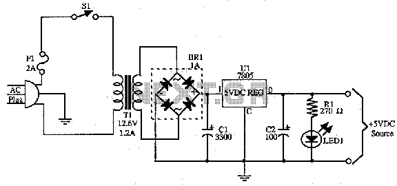
simple switching power supply 15 watt

The schematic diagram is derived from a circuit designed for a simple switching power supply with a power output of 15 watts. Further details regarding this power supply and its related circuit diagram can be found on the corresponding page.
The pulse transformer T1 is a critical component in the switching power supply circuit, facilitating energy transfer between the primary and secondary windings while ensuring voltage isolation. The choice of ferrite core material, such as M2500NMS-2 or M2000NM9, is pivotal for achieving the desired magnetic properties, which influence the efficiency and performance of the transformer. The specified cross-section of 5 mm at the 5G location, combined with a central gap, optimizes the magnetic flux and minimizes core losses during operation.
The winding configuration is designed to achieve specific electrical characteristics. The primary winding, consisting of 2 turns of 0.1 mm diameter wire, is crucial for generating the initial magnetic field. The additional turns of 0.25 mm diameter wire enhance the transformer's ability to handle higher voltages and currents. The inclusion of 5-6 turns of wire identical to the primary winding serves to increase the coupling efficiency and improve the overall performance of the transformer.
In the context of the simple switching power supply, the transformer plays a vital role in converting the input voltage to the desired output voltage while maintaining regulation and minimizing ripple. The circuit design utilizes the transformer to facilitate the switching process, allowing for efficient energy conversion and management.
For a comprehensive understanding of the operation and integration of the pulse transformer within the switching power supply, it is advisable to review the complete circuit diagram and accompanying explanations provided on the designated page. This will provide insights into the overall design philosophy, component interactions, and operational principles governing the power supply system.Pulse transformer T1 is performed on the ferrite core M2500NMS-2 or M2000NM9 Sh5h5 size (cross-section of the magnetic coils at the location of 5G—5 mm with a gap in the center). Winding wire is made brand PEL-2. Winding 1. 2 turns of wire contains 600 0. 1 mm in diameter, 3-4 44 turns of 0. 25 mm diameter, 5-6 10 turns in the same wire as the primary winding. The schematic diagram come from circuit: Simple Switching Power Supply 15 Watt power supply. Go to that page to read the explanation about above power supply related circuit diagram. 🔗 External reference
Related Circuits

This article was originally published in a slightly modified form in the QST magazine, December 1998 and January 1999, and in the Radio Amateur's Handbook, 1999. Visit the American Radio Relay League for information on these publications and a...
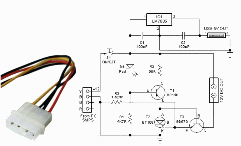
This compact circuit is designed to eliminate the clutter of surplus small AC mains adapters from a desktop environment. The circuit functions as a smart DC power box. The circuit operates by consolidating multiple AC to DC power conversions into...
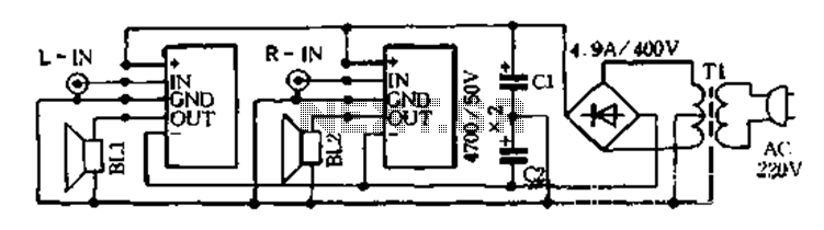
The D-200W module features a unique design that includes overload, overvoltage, overheating, short circuit, and reverse polarity protection, as well as shock protection for various speakers. The module employs a synchronous dynamic bias circuit to minimize static power consumption,...
This page is provided to the domain owner free of charge by Sedo's Domain Parking. The domain owner and Sedo do not have any relationship with third-party advertisers. References to specific services or trademarks are not controlled by Sedo...
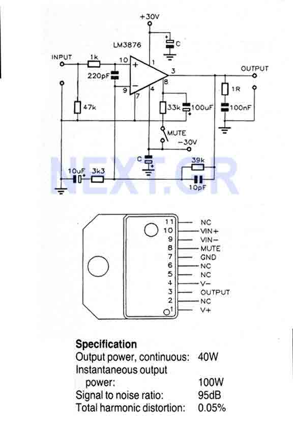
This Circuit is based on the LM3876. A 11-pin plastic package IC with high performance audio power amplifier, an output mute function which can be used to eliminate switch-on and switch-off "thumps" to the loudspeaker load. It is capable...
The input is DC biased to the mid-operating point and is AC coupled. Its input impedance is approximately 500K ohms at low frequencies. For DC loads referenced to ground, the quiescent current is increased by the load current set...