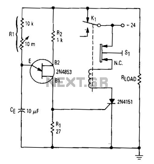
Simple-time-delay

After the first cycle, the relay will normally be energized. When the normally closed pushbutton 51 is activated, the SCR turns off, the relay is de-energized, and power is applied to the relaxation oscillator and the load. After a time delay varying from less than a second to approximately 2.5 minutes, as determined by the setting of the 10-MΩ potentiometer, the unijunction will fire and turn on the SCR. The relay will remain energized until power is removed from the oscillator and the load, and it will stay energized until button 51 is pushed again. The UJT trigger output from base 1 directly drives the gate of the SCR. However, where isolation between the UJT trigger or any other type of trigger and the thyristor power circuit is required, a simple pulse transformer can be used to interface the two elements.
The described circuit operates on a principle that combines a relay, a silicon-controlled rectifier (SCR), and a unijunction transistor (UJT) to control the timing and activation of a load. Initially, the relay is energized after the first cycle, maintaining its state until a specific action occurs. The activation of the normally closed pushbutton 51 interrupts the power to the relay, causing it to de-energize. This action simultaneously turns off the SCR, which is crucial for controlling the flow of current to the connected load and the relaxation oscillator.
The time delay feature is implemented through the adjustment of a 10-MΩ potentiometer, which influences the unijunction's firing time. The UJT serves as a timing device, and once the preset delay elapses, it triggers the SCR, allowing current to flow through the relay and the load again. This cycle can repeat as long as the system remains powered.
For applications requiring electrical isolation between the triggering mechanism and the power circuit, a pulse transformer can be integrated. This transformer ensures that any voltage spikes or noise from the UJT trigger do not affect the SCR or the load, thereby enhancing the reliability and safety of the circuit.
In summary, this circuit design effectively manages the energization and de-energization of a relay based on user input and timing, with options for isolation to protect sensitive components. The combination of a relay, SCR, UJT, and potential isolation methods provides a robust solution for various electronic control applications.After the first cycle. the relay will normally be energized. When normally closed pushbutton 51 is activated, the SCR turns off, the relay is de-energized, and power is applied to the relaxation oscillator and the load. Mter a time delay varying from less than a second to approximately 2.5 minutes, as determined by the setting of the 10-M!l potentiometer, the unijuction will fire and tum on the SCR.
The relay will energize until power is removed from the oscillator and the load, and will stay energized until button 51 is pushed again. The UJT trigger output from base 1 directly drives the gate of the SCR. However, where isolation between the UJT trigger or any other type of trigger and the thyristor power circuit is required, then a simple pulse transformer, interfacing the two elements, will suffice.