
Simple ttl crystal oscillator

The described crystal oscillator circuit utilizes a single inverter from a 7404 hex inverter IC, which contains six independent inverters. In this configuration, the inverter operates in a linear region, facilitated by the resistors R1 to R4 that set the bias point. The resistors are strategically placed to ensure that the inverter remains in a state where it can amplify the oscillations generated by the crystal.
The crystal used in this circuit is critical as it determines the frequency of oscillation. The fundamental frequency of the crystal is defined by its physical characteristics, which include its cut, size, and material. When the circuit is powered, the crystal resonates at its fundamental frequency, which is the frequency at which it naturally oscillates. This resonance creates a feedback loop that sustains oscillation, allowing the inverter to switch states and produce a square wave output.
The output frequency of the oscillator circuit is primarily determined by the characteristics of the crystal and, to a lesser extent, the values of the resistors. The circuit can be tuned for stability and performance by adjusting the resistor values, although the crystal itself will predominantly dictate the oscillation frequency. This simplicity and low component count make the crystal oscillator an ideal choice for applications requiring a stable clock signal, such as in microcontroller timing circuits, frequency generation, and signal processing tasks.
Due to its low cost and ease of implementation, this crystal oscillator circuit is widely used in various electronic devices and systems, providing a reliable frequency source for digital applications.This simple and cheap crystal oscillator comprises one third of a 7404, four resistors and a crystal. The inverters are biased into their linear regions by R1 to R4, andthe crystal provides the feedback Oscillation can only occur at the crystals fundamental frequency.
Related Circuits
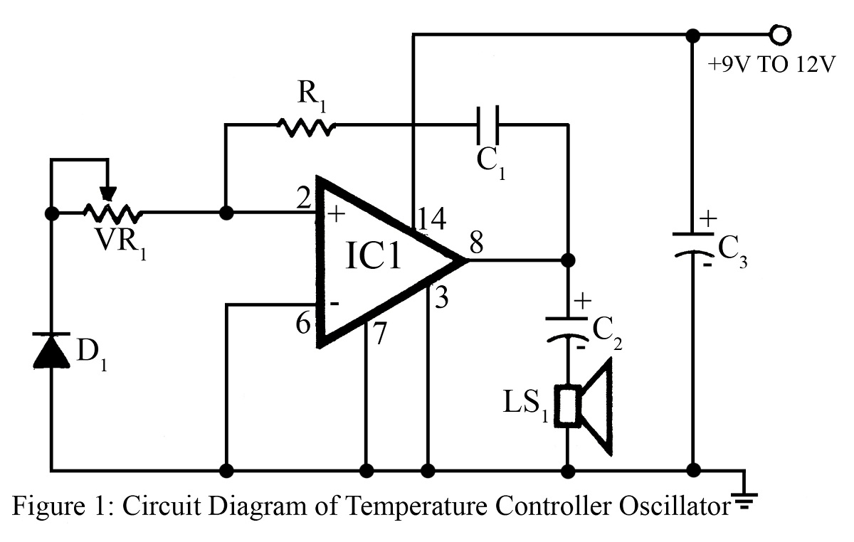
The output frequency or tone of this oscillator circuit varies with the temperature at which the input germanium diode is maintained. The reverse resistance of D1 ranges from 500 ohms to 10 k ohms when the temperature fluctuates between...

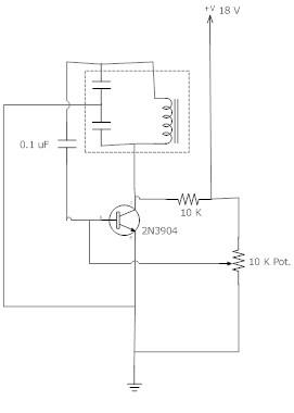
This circuit is sensitive to low-frequency electromagnetic radiation and can detect hidden wiring or the field surrounding a transformer. A radial type inductor is used as a probe, which effectively responds to low-frequency changing magnetic and electric fields. Ordinary...
The impedance of these current generators is essentially infinite for small currents, and they maintain accuracy as long as VIN is significantly greater than VOS and IO is much higher than I bias. The source employs a FET to...
An LC Colpitts oscillator is being designed based on the Colpitts oscillator configuration. The LC Colpitts oscillator is a type of electronic oscillator that utilizes an inductor (L) and two capacitors (C1 and C2) to create a feedback loop that...
An op-amp based Colpitts oscillator in Multisim displays a "timestep too small" error when the run button is pressed. Despite extensive research and attempts to resolve the issue, the error persists. The design features a C-L-C pi circuit that...
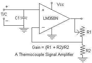
Continuing with the thermocouple interface concept, the next step is to amplify the TC's millivolt signal into a more readable analog voltage, on the order of 0 to 5VDC. This simple circuit fits the bill. The LM358N is a...