
Simple UHF oscillator

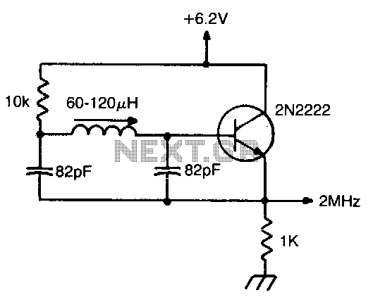
The oscillator described operates within the frequency range of 350 to 500 MHz, making it suitable for various RF applications. The use of a microstrip inductor as a PCB trace allows for compact integration within the circuit layout, which is essential for minimizing parasitic capacitance and maintaining signal integrity at high frequencies. The output power specification of 55 to 100 mW indicates that this oscillator can drive a variety of RF loads effectively, ensuring compatibility with standard 50-ohm systems commonly used in RF communications.
Frequency stability is a critical parameter for oscillators, especially in communication systems where signal integrity must be maintained. The stated stability of 0.1% over a temperature range of -20°C to 50°C suggests that the oscillator is designed to perform reliably in varying environmental conditions, which is important for outdoor or industrial applications.
The tap point, typically located 15% from the bottom end of the inductor, is crucial for achieving the desired feedback and tuning characteristics of the oscillator. This tap allows for the extraction of a portion of the signal, which is fed back into the circuit to sustain oscillation. The placement of the tap affects the overall performance, including the amplitude and stability of the output signal.
In summary, the oscillator's design leverages a microstrip inductor and is optimized for RF applications, providing stable frequency output with suitable power levels for integration into various systems. Proper attention to the tap placement and PCB layout will enhance the performance and reliability of the oscillator in practical applications.This oscillator is typical for 350 to 500 operation. The microstrip inductor is a PC board trace. The output power is 55 to 100 mW into 50, with the frequency stability typically 0.1% over to 50°C. The tap is typically 15% from the bottom end.
Related Circuits
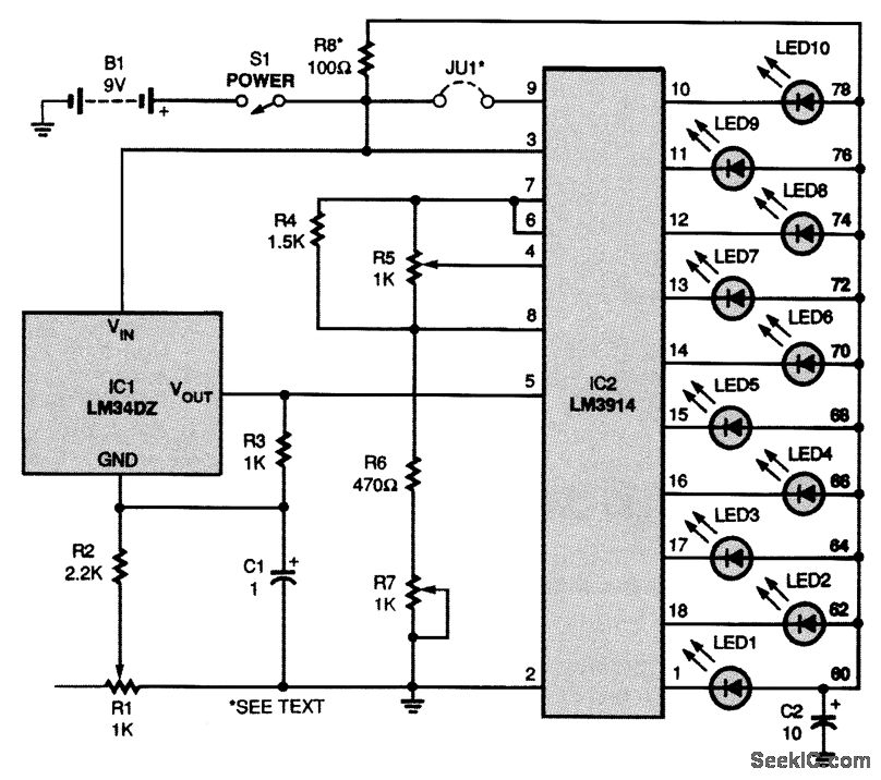
The circuit is powered by a 9-V battery (B1) but can also operate with any 7- to 10-V DC power supply. At the core of the thermometer is IC1, an LM34 temperature sensor, which generates a voltage between the...
This is a voltage controller oscillator that was designed as a wide range oscillator to generate clock pulses for a stepper motor drive system. It does however have some interesting features. The original application used a stepper motor for...

The AD9835 combines the Numerical Controlled Oscillator (NCO), COS Look-Up Table, Frequency and Phase Modulators, and a Digital-to-Analog Converter on a single integrated circuit. With more easy words you can say that this circuit is an oscillator where the...
Miller 9055 miniature slug-tuned coil; all resistors 1/4W 5%; all capacitors minimum 25 V ceramic. The Miller 9055 miniature slug-tuned coil is designed for applications requiring precise tuning and compact form factors. This coil is characterized by its miniature size,...
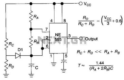
Using Rl, R7, and D1 to preset CI to one third of the supply voltage. This circuit avoids a longer first cycle period than subsequent cycles. The circuit described involves the use of resistors Rl and R7 along with diode...
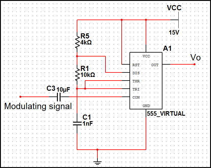
In pulse position modulation, the amplitude and width of the pulses are kept constant, while the position of each pulse with reference to the position of the reference pulse is changed according to the instantaneous sampled value of the...