
Simple variable frequency oscillator

The circuit operates primarily on the principles of astable multivibrator configuration using the 555 timer IC, which is a versatile and widely used component in electronic applications. In this setup, the 555 timer is configured to oscillate between high and low states, producing a square wave output. The frequency of this output can be varied by adjusting a potentiometer connected to the timing components of the circuit.
The essential components of the circuit include the 555 timer IC, a resistor (R1), a potentiometer (R2), and a capacitor (C1). The values of R1 and R2, along with the capacitance of C1, determine the frequency of oscillation according to the formula:
\[ f = \frac{1.44}{(R1 + 2R2) \cdot C1} \]
where:
- \( f \) is the frequency in hertz (Hz),
- \( R1 \) is the resistance in ohms (Ω),
- \( R2 \) is the resistance of the potentiometer in ohms (Ω),
- \( C1 \) is the capacitance in farads (F).
To construct the circuit, the following steps should be followed:
1. Connect pin 1 of the 555 timer to ground.
2. Connect pin 8 to the positive supply voltage (typically between 4.5V to 15V).
3. Connect R1 between pin 7 (discharge) and pin 8 (Vcc).
4. Connect the potentiometer (R2) between pin 7 and pin 6 (threshold).
5. Connect pin 6 to pin 2 (trigger).
6. Connect a capacitor (C1) between pin 2 and ground.
7. Connect pin 3 (output) to the output load or measurement device.
By adjusting the potentiometer, the resistance value changes, thus altering the timing interval and consequently the frequency of the square wave output. This circuit can be used in various applications, including tone generation, frequency modulation, and as a clock pulse generator for digital circuits. The simplicity and adjustability of this variable frequency oscillator make it a valuable tool in both educational and practical electronic projects.Simple variable frequency oscillator. This is a very simple circuit utilising a 555 timer IC to generate square wave of frequency that can be adjusted by a potentiometer. With values given. 🔗 External reference
Related Circuits
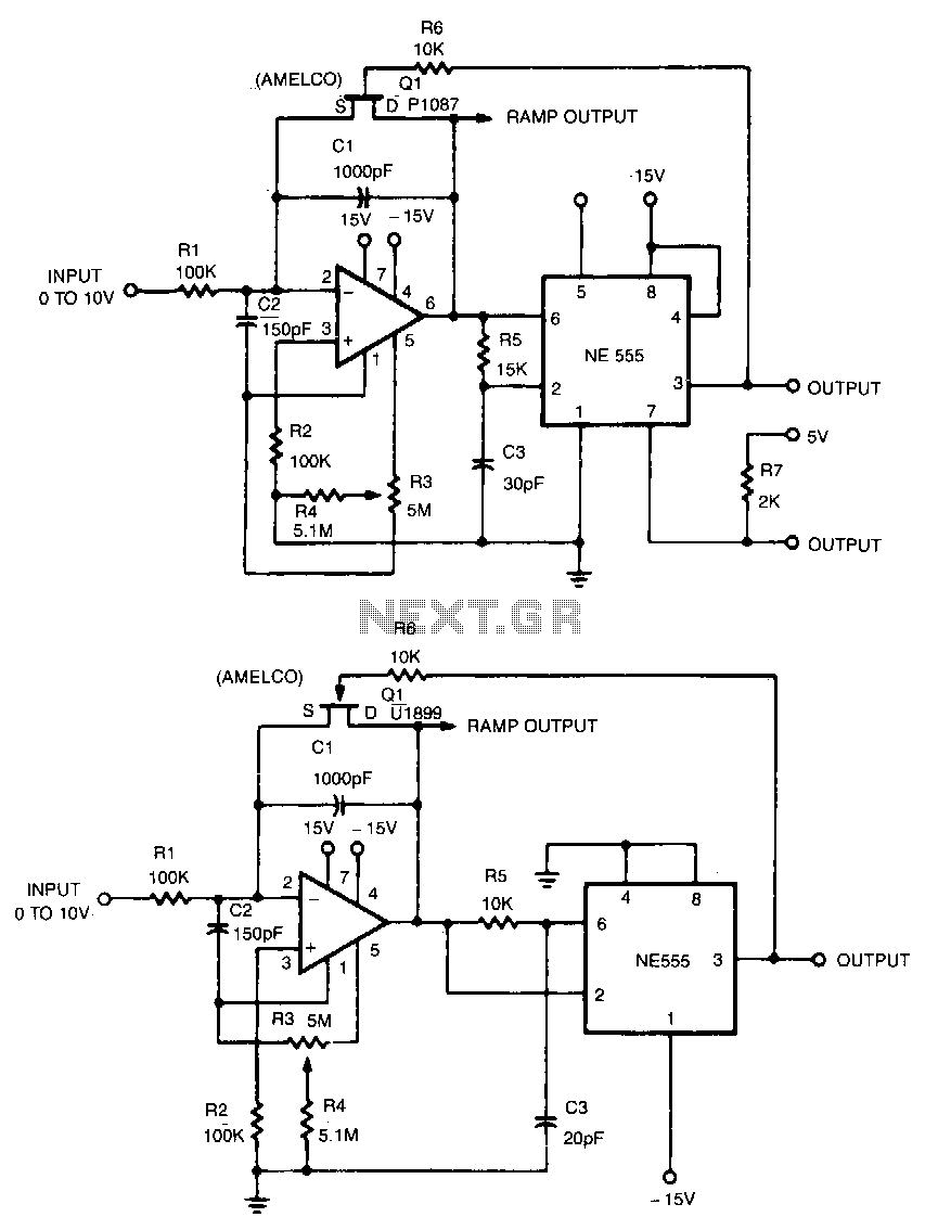
This linear voltage-to-frequency converter achieves good linearity over the range of 0 to -10 V. Its mirror image provides the same linearity over the range of 0 to +10 V; however, it is not compatible with DTL or TTL. The...

This second-order filter, designed for audio applications, utilizes an LM1458 or a similar operational amplifier. It is tunable with a cutoff frequency ranging from 30 Hz to 300 Hz. The resistors R2a and R2b are ganged log-taper potentiometers. The described...
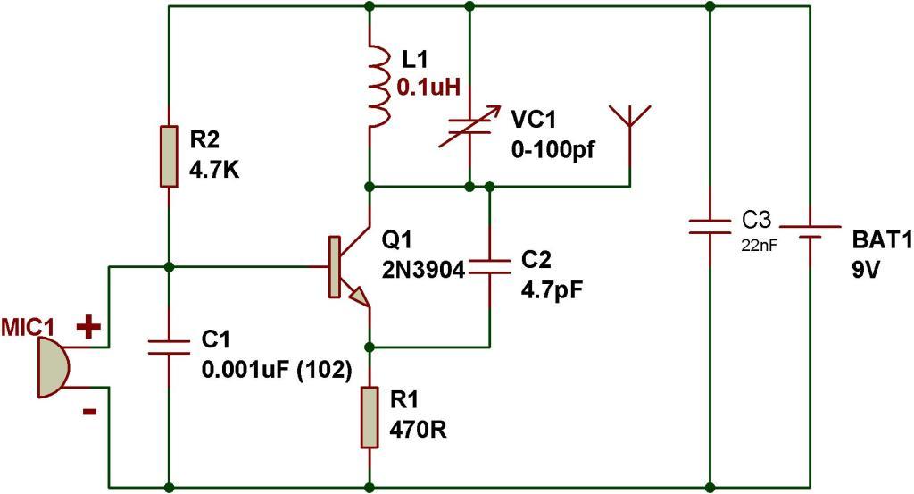
This tutorial outlines the construction of a simple FM transmitter utilizing a single transistor. The project requires minimal components, making it suitable for beginners. Before proceeding, refer to the schematic provided below, which details the components necessary for building...
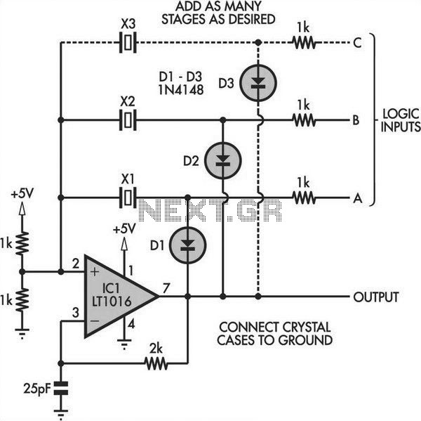
Switchable Output Crystal Oscillator Circuit. This oscillator circuit allows crystals to be electronically switched using logic commands. The circuit is best understood by initially ignoring all crystals. Furthermore, assume that a... The switchable output crystal oscillator circuit is designed to...
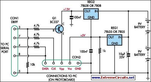
This simple programmer accepts any device supported by software. The circuit is partially based on the ISP header described in the SILICON CHIP "PIC Testbed" project and features an external programming voltage supply for laptops and other situations where...
This circuit accepts positive, negative, or differential control voltages. When the control voltage is zero, the output frequency is also zero. The described circuit functions as a versatile control voltage interface, capable of processing a range of input signals, including...