Simple-vco

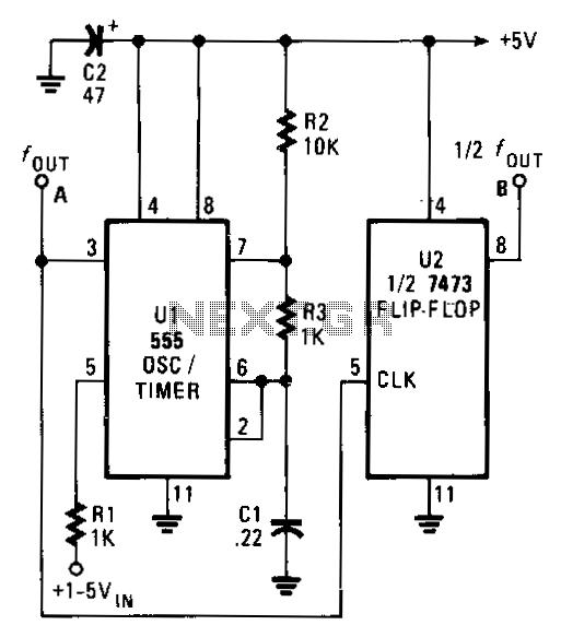
The output frequency of the voltage-controlled oscillator (VCO), U1, varies inversely with the input voltage. With a 1 V input, the oscillator output frequency is approximately 1500 Hz; with a 5 V input, the output frequency decreases to around 300 Hz. The output frequency range of U1 can be modified by changing the values of capacitors C1 and resistors R2 and R3. Increasing the value of any of these three components will reduce the oscillator frequency, while decreasing any of these values will increase the frequency. The symmetry of the output waveform is affected as the frequency transitions from one extreme to the other. At the highest frequency, the waveform is nearly symmetrical. However, as the frequency decreases, the circuit output becomes a narrow pulse. To achieve a symmetrical waveform, a second integrated circuit, U2, which is half of a 7473P dual TTL J-K flip-flop, can be added to the oscillator circuit. The signal frequency output by U2 is half of the input frequency.
The voltage-controlled oscillator (VCO) U1 operates by producing an output frequency that is inversely proportional to the input voltage. This relationship allows for a broad range of frequency outputs based on the input voltage levels applied. The frequency output can be adjusted within a specific range by varying the capacitance of C1 and the resistance values of R2 and R3. The design principle here is that increasing the capacitance or resistance will lead to a decrease in the frequency output, while reducing these values will result in an increase in frequency.
It should be noted that the output waveform's symmetry is compromised as the frequency moves from high to low. At higher frequencies, the waveform maintains a near-equal division, whereas at lower frequencies, the output transitions into a narrower pulse shape, which may not be desirable in applications requiring a symmetrical waveform.
To rectify the issue of waveform symmetry, the integration of a second IC, U2, which functions as a J-K flip-flop from the 7473P series, is recommended. This component effectively divides the frequency output from U1 by two, thereby improving the symmetry of the output waveform. The addition of U2 enhances the overall performance of the circuit, allowing for more precise control over the output characteristics and making it suitable for various applications that demand a stable and symmetrical waveform.The output frequency of the VCO, U1, varies inversely with the input voltage. With a 1 "V input, the oscillator output frequency is about 1500 Hz; with a 5-V input, the output frequency drops to around 300 Hz. The output frequency range of U1 can be altered by varying the values of C1, R2, and R3. Increasing the value of any those three components will lower the oscillator frequency, and decreasing any of those values will raise the frequency.
Output-waveform gymmetry suffers since the frequency varies from one extreme to the other. At the highest frequency, the waveform is almost equally divided. But when the frequency drops, the output of the circuit turns into a narrow pulse. If a gymmetrical waveform is required, add the second IC, U2, half of a 7473P dual TTL J-K flip-flop, to the oscillator circuit. The signal frequency output by U2 is "iz of the input.