
Simple Video Amplifier

The video amplifier circuit is designed to enhance video signals while ensuring the integrity of the transistors involved. The circuit features two primary potentiometers, P1 and P2, which adjust the black level and signal amplitude, respectively. The potential risk arises when these potentiometers are set to their extremes, which can lead to excessive base currents flowing into the transistors T1 and T2.
To prevent transistor damage, resistors R3 and R4 are strategically placed in the circuit. These resistors act as current limiters, effectively capping the base currents to a safe level of no more than 5 mA. This precautionary measure is critical in maintaining the reliability and longevity of the transistors under varying operational conditions.
Additionally, the shunt capacitor C4 is included in the design to ensure that the resistor R4 does not adversely affect the overall amplification of the video signal. By providing a low-impedance path to ground for high-frequency signals, C4 helps maintain the desired frequency response and stability of the amplifier circuit.
Overall, the careful selection of components and their configuration in this video amplifier circuit not only enhances performance but also safeguards against potential damage, making it a robust solution for video amplification applications.The video amplifier in the diagram is a well-known design. Simple, yet very useful, were it not for the ease with which the transistors can be damaged if the potentiometers (black level and signal amplitude) are in their extreme position. Fortunately, this can be obviated by the addition of two resistors. If in the diagram R3 and R4 were direct co nnections, as in the original design, and P1 were fully clockwise and P2 fully anticlockwise, such a large base current would flow through T1 that this transistor would give up the ghost. Moreover, with the wiper of P2 at earth level, the base current of T2 would be dangerously high. Resistors R3 and R4 are sufficient protection against such mishaps, since they limit the base currents to a level of not more than 5 mA.
Shunt capacitor C4 prevents R4 having an adverse effect on the amplification. 🔗 External reference
Related Circuits
In the circuit exists a simple power amplifier 60W in the 8 ohm and 80W in the 4 ohm, with components that sure exist in big quantities. It can be used in home cinema systems or in other uses....
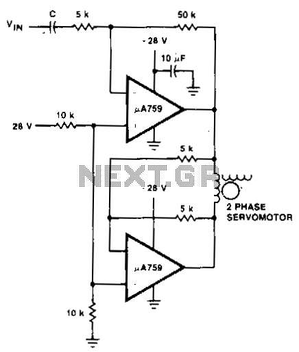
This motor driver circuit utilizes a p.A759 power amplifier to drive a two-phase servomotor. The motor driver circuit is designed to efficiently control a two-phase servomotor, leveraging the capabilities of the p.A759 power amplifier. This amplifier is specifically chosen for...
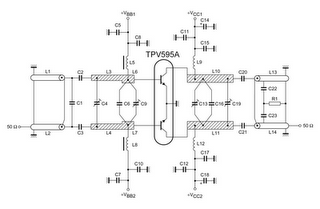
TV RF Power Amplifier 14W. This RF power amplifier operates within the frequency range of 470 - 860 MHz, covering UHF Band IV and V, and delivers an output power of 14 Watts with an input power of 1.5...
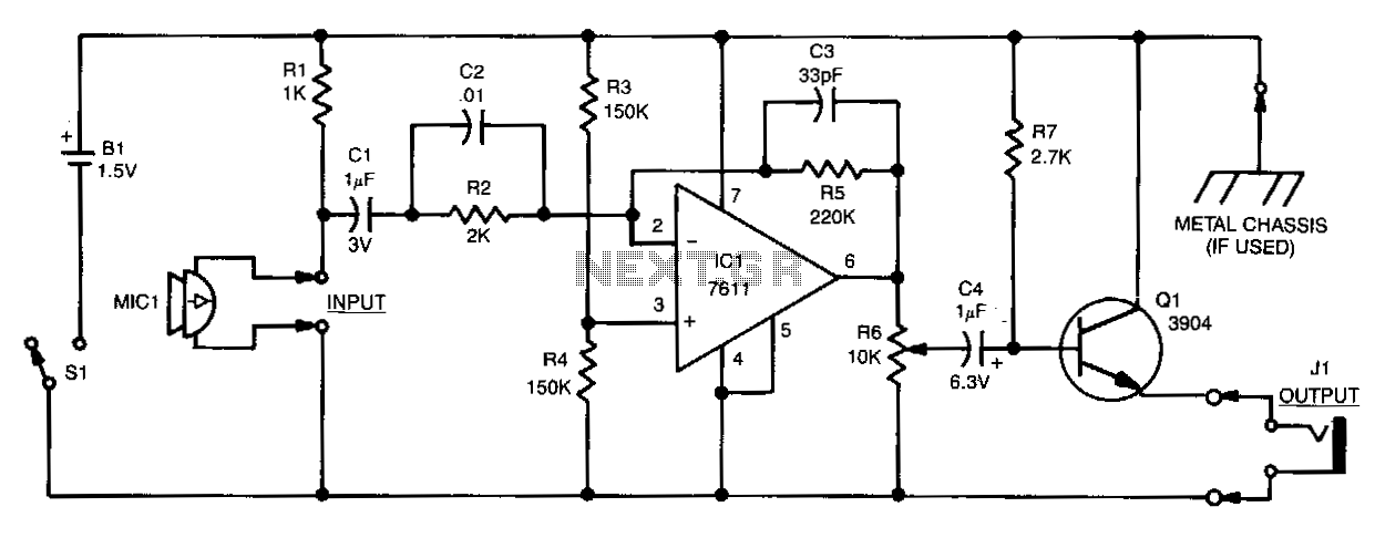
Sound detected by the electret microphone MIC1 is fed to the input of IC1 through resistor R2 and capacitors C1 and C2. Resistors R2 and R5 determine the overall gain of the stage, while C2 partially influences the amplifier's...
A 30W Class AB power amplifier circuit diagram utilizes a power transistor. To set up the amplifier, adjust the variable resistor R1 to its maximum value and R12 to zero. After completing this setup, activate the amplifier. Adjust R1...
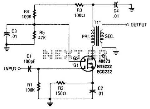
A MOSFET is utilized as a wideband buffer amplifier. T1 is wound on a toroid of approximately specified diameter, using material suitable for the frequency range, typically between 1 MHz and 20 MHz. The turns ratio should be approximately...