
Simple Voltmeter

The circuit is designed to measure low-impedance voltage sources effectively, utilizing a combination of passive and active components to achieve accurate readings. The potentiometer P1 allows for adjustable scaling of the input voltage, while resistor R1 is selected based on the expected voltage range to ensure that the voltage divider provides a suitable output for further processing. The buffering stage using transistor T1 is critical; it isolates the voltage divider from the subsequent circuit elements, preventing loading effects that could distort the measurement.
Reference diode D1 serves a dual purpose: it not only clamps the output voltage to a maximum of 2.5 V, protecting downstream components from overvoltage conditions, but it also provides a stable reference point for the circuit's operation. Resistor R3 is strategically placed to limit the current flowing into D1, ensuring that it operates within its specified limits.
The indicator stage, which includes transistor T2 and LED D2, functions as a visual feedback mechanism. When the input voltage exceeds the clamping threshold set by D1, the LED will gradually illuminate, providing a clear indication of the voltage level. Resistor R4 is used to control the current through the LED, ensuring it operates efficiently without exceeding its ratings.
Overall, this circuit provides a reliable and user-friendly solution for voltage measurement in low-impedance applications, combining precision and visual feedback in a compact design. The selection of components and their arrangement is crucial for achieving the desired performance, making this circuit suitable for various electronic measurement tasks.This circuit provides a simple means to determine the voltage of a low-impedance voltage source. It works as follows. P1, which is a 1-W potentiometer, forms a voltage divider in combination with R1. The voltage at their junction is buffered by T1, and then passed to reference diode D1 via R3. D1 limits the voltage following the resistor to 2. 5 V. An indicator stage consisting of T2, R4 and LED D2 is connected in parallel with D1. As long as the voltage is not limited by D1, the LED will not be fully illuminated. This is the basic operating principle of this measurement circuit. 🔗 External reference
Related Circuits
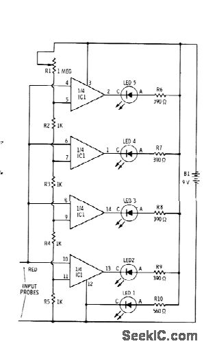
Sections of the RS339 quad comparator each drive an LED to indicate four different input voltage levels. LED 1 is connected to ground to serve as a zero indicator. The resistors depicted are intended for Radio Shack 276-041 red...
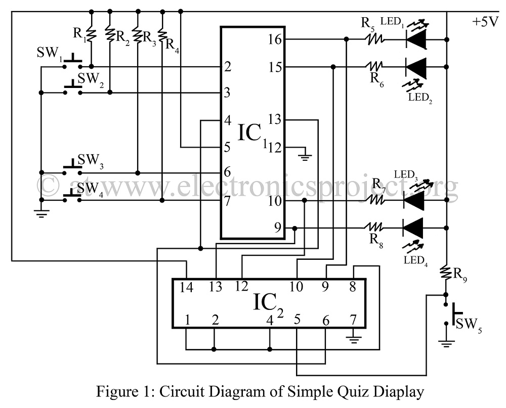
A simple quiz display is constructed using two TTL ICs: the 7445 and the 7420. It indicates which switch is pressed first, accompanied by a circuit diagram. This project represents an interesting and verified game concept. The circuit utilizes the...
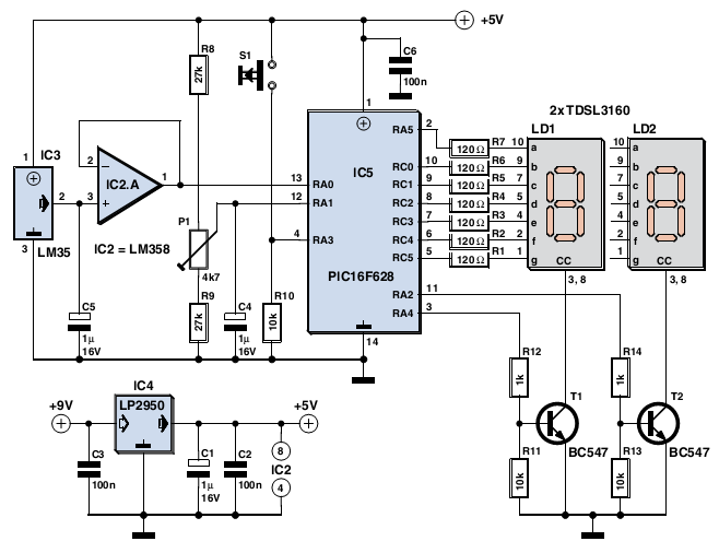
The device is user-friendly and consumes minimal current, allowing it to operate throughout the battery's shelf life. It employs a standard LM35DZ sensor (IC3) whose analog output voltage is buffered by an LM358 (IC2A). The voltage is processed by...
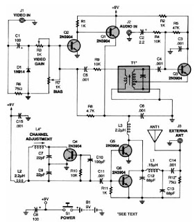
A low-power VHF TV transmitter is an essential tool for video enthusiasts, allowing the transmission of signals from a VCR to any television in a home or backyard setting. This device enables the convenience of watching movies by the...
The 555 IC is configured in an astable mode, producing a frequency that remains constant and is independent of the duty cycle. The total resistance (Rcharge + Rdischarge, considering the diode) is fixed at 22 kΩ, yielding a frequency...
The circuit shown below is a basic latching circuit consisting of a quad 2-input NAND Gate IC. It is configured such that the flip flop circuit U1A and U1B has both its input held at logic "1". Pin 1...