
Simple Wien-Bridge Oscillator

The described circuit utilizes a Wien-bridge oscillator configuration, which is renowned for generating low-distortion sine waves. In this implementation, an incandescent lamp is strategically integrated into the feedback loop of the oscillator. The nonlinear resistance of the lamp filament plays a crucial role in stabilizing the amplitude of the oscillation. As the voltage across the filament increases, its resistance changes, effectively providing automatic gain control that helps maintain a consistent output amplitude.
The Wien-bridge oscillator consists of a combination of resistors and capacitors that determine the frequency of oscillation. In this case, resistors R1 and R2, as well as capacitors C1 and C2, are pivotal in setting the operational frequency. Modifying the values of these components alters the time constants within the circuit, thus allowing for precise tuning of the output frequency. The relationship governing the frequency (f) of oscillation can be expressed as:
f = 1 / (2πRC)
where R is the equivalent resistance and C is the equivalent capacitance of the circuit.
In practice, the circuit is designed to provide a sine wave output that closely approximates an ideal waveform, minimizing harmonic distortion. This is particularly beneficial in applications where signal purity is critical, such as in audio signal generation or testing. The use of an incandescent lamp not only aids in shaping the output waveform but also introduces a unique characteristic of self-regulation, which can enhance the stability of the oscillator under varying load conditions.
Overall, the Wien-bridge oscillator with an incandescent lamp is an effective solution for applications requiring high-quality sine wave generation, with the added advantage of being easily tunable through component adjustments.Incandescent lamp has been used to reduce harmonic distortion in sine oscillator circuit. The nonlinear resistance characteristic of the lamp filament help the circuit to shape the signal to approximate the ideal sine wave. Here is the classic Wien-bridge oscillator circuit using the incandescent lamp.. You can change the frequency of the oscillator by modifying the R1 (and R2), or C1 (and C2). 🔗 External reference
Related Circuits
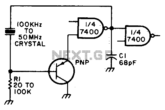
Adjust Rl for approximately 2 volts at the output of the first gate. Additionally, adjust Cl for optimal output. In the context of electronic circuit design, the output voltage of a gate, such as a logic gate or operational amplifier,...
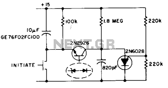
This circuit functions as both an oscillator and a timer. The 2N6028 transistor remains in an 'on' state due to the excessive holding current flowing through the 100 kΩ resistor. When the switch is briefly closed, the 10 µF...
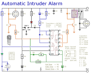
This is a simple single-zone burglar alarm circuit. Its features include automatic exit and entry delays and a timed bell/siren cut-off. It is designed to be used with the usual types of normally-closed input devices such as magnetic reed...
This is a simple JFET pierce crystal oscillator. A wide frequency range of crystals can be used with this circuit without requiring any modifications. The JFET pierce crystal oscillator is a versatile circuit that utilizes a Junction Field Effect Transistor...

To achieve a 1000:1 sweep range, the voltage across the external resistors Ra and Rb must be reduced to nearly zero. This necessitates that the maximum voltage on control pin 8 surpasses the voltage at the top of Ra...
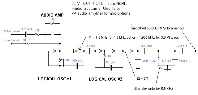
A single integrated circuit (IC) provides all amplifiers: the 74HC04 Hex Inverter, which is a digital component. The second oscillator synchronizes to three times the frequency of the first oscillator, thereby tripling the frequency modulation (FM) deviation. Utilizing the...