
Sinewave Oscillator

This circuit design represents a Wien bridge oscillator, which is known for its ability to produce stable sine wave outputs. The primary configuration involves an operational amplifier (op-amp) as the core active component, which is responsible for signal amplification and shaping. The choice of the LM107 op-amp is significant due to its low noise characteristics and stability at low frequencies, making it suitable for sine wave generation.
The frequency of oscillation is primarily determined by the values of the passive components, specifically resistors and capacitors, in the feedback network. In this circuit, a combination of resistors and capacitors is arranged to create a feedback loop that sustains oscillation at the desired frequency. The passive components must be carefully selected to ensure that the frequency remains at 10Hz. Any deviations from these values will result in a different frequency output.
The use of a FET in the feedback path enhances the circuit's performance by allowing for dynamic adjustment of the feedback resistance. This is crucial for maintaining the amplitude stability of the oscillation. The gate voltage applied to the FET controls the drain-source current, which in turn modifies the effective resistance of the feedback network, enabling the circuit to self-regulate.
Power supply decoupling is an important aspect of this design. Although not explicitly shown in the schematic, it is essential to include bypass capacitors close to the power supply pins of the op-amp. This minimizes the effect of power supply noise on the oscillator's performance. The recommended value of 0.01uF is effective in filtering high-frequency noise, ensuring a clean power supply for the op-amp.
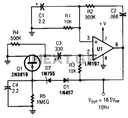
In summary, this circuit is a robust example of a Wien bridge oscillator, capable of generating a stable 10Hz sine wave output. Its design emphasizes the importance of component selection, particularly for passive elements that dictate frequency, and highlights the role of feedback control in maintaining oscillation amplitude. Proper power supply management further enhances the reliability and performance of the oscillator.This circuit, using a minimum amount of parts generates a 10Hz sine wave [based on the component values shown]. The active components are generic devices and may be substituted as required. The passive component values set the frequency and should only be changed if a different frequency is desired.
The component out lines or package styles are co mpletely irrelevant to the design. Also see a Cosine Oscillator. The active components used in this circuit are basically general purpose low power parts. The example part numbers could easily be replaced by similar to substitute parts. The zener diode is selected for the maximum voltage level of the output, so any substitute part should use the same zener voltage. However the passive parts set the frequency of operation and should not be substituted. Although any package style could be used, as long as the final value remains the same. The FET is used as a feedback path. The voltage applied to the Gate causes the Drain/Source current to vary which reduces the effective resistance of the 500k resistor in parallel with it.
No bypass capacitors are shown connected to the voltage supply of the Op Amp, but power supply bypassing should always be used. Low inductance capacitors placed near the body of the device and close to the supply leads is recommended.
Short traces between the device and capacitor is also desired. A standard value of 0. 01uF should provide adequate filtering of the power line and reduce any noise reaching the device over the power line. The sinewave oscillator to the right is another example of a Wien bridge oscillator. This example uses an LM107 operational amplifier and component values to produce a 70Hz sine wave. 🔗 External reference
Related Circuits
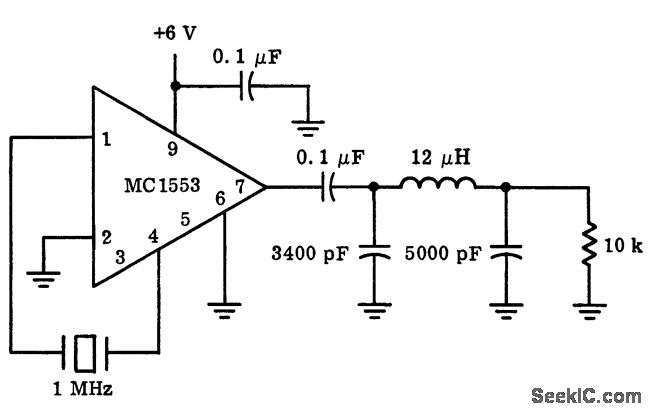
These are resonant circuits or tank circuit oscillators. They are commonly used to produce high frequencies ranging from 1 MHz to 500 MHz; hence, they are also known as RF oscillators. These oscillators are utilized in RF generators, radio...
More: The provided input lacks specific details or context regarding an electronic circuit or schematic. To create a comprehensive electronic schematic description, it is essential to include key components, their interconnections, and the overall functionality of the...
This Wien-bridge sine-wave oscillator utilizes a 2N3819 as an amplitude stabilizer. The 2N3819 functions as a variable-resistance element within the Wien bridge. The Wien-bridge oscillator is a type of electronic oscillator that generates sine waves. It employs a bridge circuit...
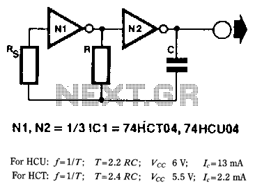
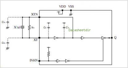
When frequency stability is not of primary importance, a simple yet reliable digital clock oscillator can be constructed using relatively few components. High-speed CMOS (HCU/HCf) inverters or gates with an inverter function are particularly suitable for creating such oscillators...
This circuit generates a stable 1 kHz sine wave using the inverted Wien bridge configuration (C1-R3 & C2-R4). It features a variable output, low distortion, and low output impedance to ensure good overload capability. A small filament lamp provides...
SEL2411AA is a sub-package of SEL2410. For a detailed description, please refer to SEL2410. The datasheet for SEL2411AA can be downloaded from the link provided below. By Pericom Semiconductor Corporation. The SEL2411AA is a specialized electronic component that serves as...