
Single IC chip Motor Driver for robots

A motor driver is an essential component in robotic applications, particularly in mobile robots such as walkers. The primary function of a motor driver is to control the power supplied to the motors, enabling precise movement and control. In this context, the motor driver allows for the amplification of current, which is crucial when the existing circuit cannot provide sufficient power to drive the motors effectively.
The described motor driver circuit utilizes the ALS245 integrated circuit, which is a dual-channel, high-speed, bidirectional level shifter and buffer. Each ALS245 can supply a maximum output current of 50mA, which may be inadequate for applications requiring higher power. Therefore, to achieve the necessary current levels for driving motors, multiple ALS245 units can be stacked together. By stacking two ALS245 chips, the total output current is effectively increased to 100mA. However, for most applications, this may still fall short of the required power, necessitating the stacking of additional drivers. It is generally recommended not to exceed three stacked units, as this provides a balance between power requirements and circuit complexity.
In practical implementation, the motor driver connections are straightforward. The user is instructed to identify the motor connections, denoted as (M), and connect them to the input terminals of the motor driver. This configuration allows for direct control of the motor's operation through the driver, thus facilitating enhanced performance.
When designing a circuit with this motor driver, it is crucial to ensure that the power supply can accommodate the total current drawn by the stacked drivers and the motors. Additionally, proper thermal management should be considered, as increased current can lead to heating in the drivers, which may affect performance and reliability. Overall, this motor driver setup provides a flexible and effective solution for driving motors in robotic applications, particularly when higher current levels are required.A motor driver! I'm sure you knew that already but that's what it is. A motor driver is required in pretty much all walkers including all of my CW series walkers. You need to use it any time you need to supply more current to the motors because the circuit can't supply enough. I like this one because it's very easy to build and pretty flexible on what you can do with it. Just find the (M) and take the two connections going to it and hook them to the inputs of the driver.
Stack 'em up Q - When I hook my motor directly to the battery it has lots of power but when I hook it to the motor driver it doesn't and can't even move my walkers leg. A - Each driver supplies 50mA and since they are already doubled up you have 100mA which in most cases is not enough. The answer, stack 'em. You can see in the image on the right that all you have to do is stick another ALS245 on top and solder it on.
It's that easy. You can stack as many as you need but you shouldn't need more than 3 and 2 should be plenty. 🔗 External reference
Related Circuits
For controlling a small DC motor, such as the one found in a tape recorder, Q1 and Q2 are in saturation when both points A and B are HIGH. Component: .. To control a small DC motor effectively, a circuit...
The ADM3251E is a transceiver that features high-speed operation, 2.5 kV full isolation, and a single channel for RS-232/V.28 communication. This device operates from a single 5 V power supply. The ADM3251E transceiver is designed for robust communication in environments...
The TDA2549 is a complete intermediate frequency (IF) circuit that includes automatic frequency control (AFC), automatic gain control (AGC), demodulation, and video preamplification capabilities for multistandard television receivers. It can process both positively and negatively modulated video signals in...
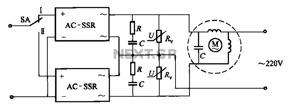
The circuit illustrated in Figure 3-14 features a SA switch positioned in the work state, allowing for motor operation. When the SA switch is set to the reverse position, the motor's direction is inverted. Additionally, an over-voltage protection element...
This preamplifier has a low output impedance, and is designed to drive long cables, allowing you to listen to a remote music source without having to buy expensive screened cables. The very low output impedance of around 16 ohms...
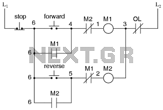
This is the power diagram for motor forward and reverse operation. To change the motor direction, one polarity must be altered, for example, changing R to S. For detailed information, please refer to the following. The described power diagram illustrates...