
Small FM Radio Circuit

The FM radio receiver circuit typically consists of several key components that work together to demodulate the frequency-modulated signals transmitted by local radio stations. The main components of this circuit include an antenna, a radio frequency (RF) amplifier, a mixer, a local oscillator, an intermediate frequency (IF) amplifier, a demodulator, and an audio amplifier.
The antenna captures the radio signals, which are then amplified by the RF amplifier to improve the signal strength. The amplified signal is fed into the mixer, where it is combined with a signal from the local oscillator. This mixing process produces an intermediate frequency that is easier to process than the original RF signal.
The IF amplifier further boosts the intermediate frequency signal, which is then passed to the demodulator. The demodulator extracts the audio information from the modulated carrier wave, converting it into an audio signal that can be amplified by the audio amplifier. Finally, the audio output can be connected to a speaker or headphones for listening.
The simplicity of this FM radio receiver design makes it accessible for hobbyists and beginners in electronics, while still providing reliable performance for receiving FM broadcasts. The compact size allows for easy integration into various devices or projects, making it a versatile choice for anyone interested in building their own radio receiver.Perhaps this is one of the simplest and smallest FM radio receiver that can receive the FM stations available locally. Its simple design makes it ideal for.. 🔗 External reference
Related Circuits
Most IR remotes operate effectively within a range of 5 meters. The complexity of the circuit increases when designing the IR transmitter for reliable operation over longer distances, such as 10 meters. To extend the range from 5 meters...

This is an application circuit for calibration known as a high voltage AC calibrator circuit. A key aspect of sine wave oscillator design is the stable control of amplitude. In this circuit, the amplitude is stabilized through servo control,...
This page is browser-friendly. To enhance readability, adjust your browser window to be narrower than the full screen. The page consists of two parts: the first part features a basic program demonstrating the RFID reader's functionality, while the second...
Modify a zapper circuit (similar to the Hulda Clark Zapper) to produce two different frequencies. One switch should be used to set the pulse to 15Hz, and another switch to set it to 30Hz. The nominal frequency for this...
This page is provided to the domain owner free of charge by Sedo's Domain Parking. The domain owner and Sedo do not have any relationship with third-party advertisers. References to any specific service or trademark are not controlled by...
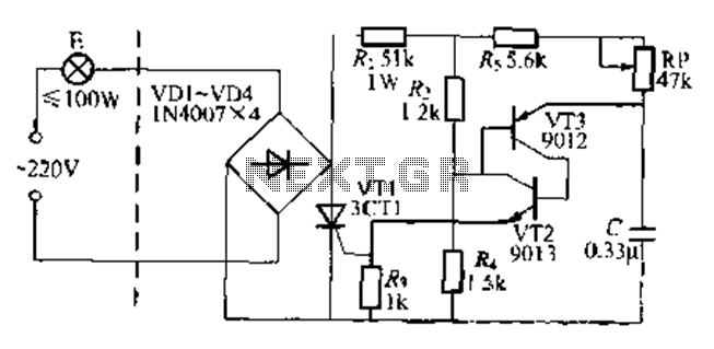
The circuit is a one-way ordinary transistor-triggered dimmer light circuit. It uses a complementary amplifier configuration with transistors VT2 and VT3 to form the thyristor trigger circuit for VT1. The circuit operates with a 220V alternating current through the...