
SMPSU With A Relay

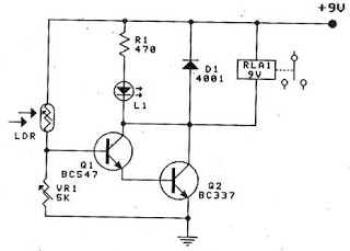
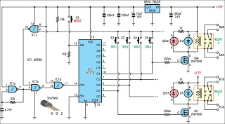
The described switched mode power supply unit (SMPSU) circuit utilizes a relay-based design to achieve a step-up voltage conversion. The relay, designated as Re1, operates in a way that it alternately opens and closes its contacts, creating a pulsed output. This pulsing action is essential for the operation of the circuit, as it allows for the storage of energy in the magnetic field of the relay coil.
When power is first applied, the relay coil is energized, creating a magnetic field that holds the relay in its activated position. As the circuit oscillates, the relay will eventually release, which interrupts the current flow momentarily. The sudden interruption leads to the collapse of the magnetic field, which induces a high voltage in the coil due to Faraday's law of electromagnetic induction. This induced voltage is rectified by diode D1, which allows current to flow in one direction, and is then smoothed by capacitor C1 to provide a more stable DC output.
The output voltage, approximately 150 V, is influenced significantly by the characteristics of the relay used in the circuit. Faster relays tend to produce higher induced voltages due to their quicker response times, resulting in more efficient energy transfer during the oscillation cycle. The oscillation frequency, typically ranging from 100 to 200 Hz, is determined by the relay's mechanical properties and the circuit's design parameters. The audible buzzing sound that accompanies this operation is a direct result of the relay's rapid switching action.
Overall, while this circuit serves as a foundational educational tool for understanding step-up switch mode circuits, it is essential to recognize that practical implementations of SMPSUs require careful consideration of component selection, safety measures, and design optimization to ensure reliable and efficient operation.Switched mode power supply units (SMPSUs) are popular but difficult to build oneself as well problematic when it comes to understanding their design principles. Building your own SMPSU typically requires a lot of expertise, hard to find components and time. The circuit shown here is educational only and devised to demonstrate the principle of the step-up switch mode circuits. It is not intended to be incorporated in a real` design. Relay Re1 has a normally-closed (NC) change-over contact and is connected toact as a vibrator. When power is applied to the circuit, the relay is energized and actuates its contact. This action may appear to break the circuit. However, the energy stored in the relay coil will produce an induced voltage which is fed to D1 and C1 for rectification and smoothing. The output voltage will be of the order of 150 V and strongly dependent on the type of relay used. In general, the faster the relay, the higher the output voltage. The circuit will oscillate at a low frequency (100-200 Hz), and a buzzing sound will be heard from the relay.
🔗 External reference
Related Circuits
All files are found using legitimate search engine techniques. This site does not condone hacking into sites to create the links it lists. It is assumed that all links found on the search engines used are obtained legally and...
The circuit diagram represents a water-activated relay circuit. This circuit employs two transistors configured as a high-gain compound pair. The transistors used are 2N2222A for T1 and T2, which may also be substituted with BC108. The current gain is...
The circuit operates continuously, turning on and off. It utilizes the widely recognized NE555 timer IC, known for its versatility in various electronic applications. In this configuration, the IC is set up as an astable multivibrator. A 12-volt relay...
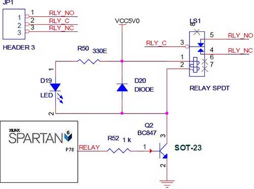
The Spartan-6 board features onboard 5V relay interfacing, as illustrated in the accompanying figure. The ULN2803 serves as a driver for the FPGA I/O lines, with the driver's outputs connected to the relay modules. A PTB connector is provided...
This circuit is designed for use in a hi-fi showroom, allowing for the selection of different speakers to connect to a stereo amplifier for comparative listening. It can also serve similar applications where only one device from a set...

The schematic below illustrates four methods of controlling a relay with a digital logic signal. Figure A can be used in most cases where the relay coil requires 100 mA or less and the input current is 2 milliamps...