
Soft Musical Telephone Ringers

The circuit operates by utilizing a combination of transistors, diodes, capacitors, and an integrated circuit to effectively modify the telephone ringing signal. The primary detection mechanism involves transistor T1, which is activated by the incoming ringing voltage. When the telephone rings, the positive half-cycle of the AC signal forward biases diode D1, allowing current to flow into the base of transistor T1. This action causes transistor T1 to conduct, leading to the discharging of capacitor C2, which in turn cuts off transistor T2.
Transistor T2 is critical in controlling the state of IC1 (UM66), which is a melody generator IC. When T2 is turned off, IC1 is activated, allowing it to produce a musical tone through the speaker connected to transistor T3. The output from IC1 is determined by the specific melody programmed into the IC, creating a pleasant sound in place of the harsh ringing of the telephone.
The circuit is designed to ensure that during the negative half-cycle of the ringing voltage, capacitor C2 remains charged, preventing the activation of IC1 and maintaining the soft musical output only during the ringing intervals. This synchronization ensures that the musical tone aligns with the ringing signal, providing a seamless transition from a disruptive noise to a soothing melody.
Overall, this circuit is an innovative solution for enhancing the user experience by replacing the traditional telephone ring with a more enjoyable auditory signal, effectively addressing the annoyance associated with conventional telephone bells.The normal telephone bell, at times (specially during night when one does not want to be disturbed), appears to be quite irritating. The circuit shown here converts the loud sounding bell into a soft and pleasing musical tone. The incoming ring is detected by transistor T1 and components wired around it. In absence of ringing voltage, transistor T 1 is cut off while transistor T2 is forward biased as resistor R2 is returned to the positive supply rails. As a result collector of transistor T2 is at near-ground potential and hence IC1 (UM66) is off. Also capacitor C2 is charged to a slightly positive potential. During positive half of the ringing voltage, diode D1 forward biases transistor T1 and rapidly discharges capacitor C2 to near ground potential and cuts off transistor T2 which, in turn, causes IC1 to be forward biased and music signal is applied to base of transistor T3 which drives the speaker.
During negative half of the ringing voltage, capacitor C2 cannot charge rapidly via resistor R2 and hence transistor T2 remains cut off during the ringing interval. Thus the soft musical note into the loudspeaker sounds in synchronism with the ringing signal. When handset is lifted off the cradle, the ringing voltage is no more available and hence the soft musical note switches off.
🔗 External reference
Related Circuits
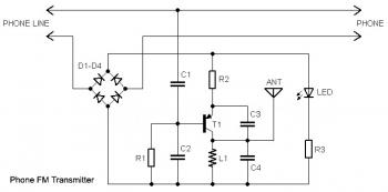
This circuit connects in series with a home phone line and transmits phone conversations through the FM band whenever the telephone handset is picked up. The transmitted signal can be tuned by any FM receiver. The circuit includes an...
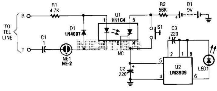
The circuit is constructed using a pair of low-cost integrated circuits (ICs): an H11C4 optoisolator/coupler with a silicon-controlled rectifier (SCR) output (U1) and an LM3909 LED flasher (U2). It connects to the phone line in the same way as...

A compact, inexpensive and low component count telecom headset can be constructed using two readily available transistors and a few other electronic components. This circuit is very useful for hands-free operation of EPABX and pager communication. Since the circuit...
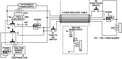
A two-line intercom with a telephone changeover switch. This circuit can connect two telephones in parallel and function as a 2-line intercom. Typically, a single telephone is connected to a. The two-line intercom circuit is designed to facilitate communication between...
The project concept originated nearly two years ago during research for a new lighting board for a small theater. The existing board was nearly twenty years old and in dire need of replacement. However, the costs associated with purchasing...
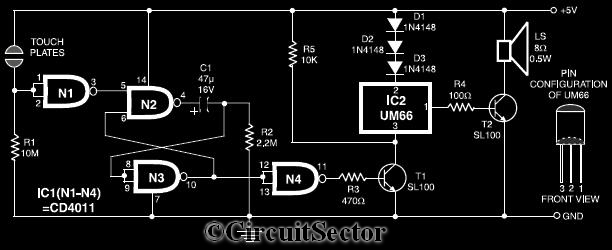
This circuit diagram illustrates a touch-sensitive musical bell based on the UM66 melody generator IC. The design incorporates a CMOS IC CD4011 and features a pair of touch plates. When these plates are briefly bridged by a hand, the...