
solar battery charger circuit

The solar battery charger circuit is designed to convert solar energy into electrical energy for charging 12V lead-acid batteries. The fundamental components of this circuit include a solar panel, a charge controller, a battery, and necessary protection elements.
The solar panel serves as the primary energy source, converting sunlight into direct current (DC) electricity. The output voltage of the solar panel must be higher than the battery voltage to ensure efficient charging. Typically, a solar panel rated at around 18V is used to charge a 12V battery, allowing for voltage drops and losses.
The charge controller is a critical component that regulates the voltage and current coming from the solar panel to the battery. It prevents overcharging by disconnecting the solar panel from the battery when the battery reaches a full charge, thereby protecting the battery's lifespan. Additionally, the charge controller may include features such as a low-voltage disconnect to prevent excessive discharge of the battery.
The lead-acid battery, or SLA battery, stores the energy generated by the solar panel. These batteries are commonly used due to their reliability and cost-effectiveness. It is essential to select a battery with appropriate capacity based on the intended application and energy requirements.
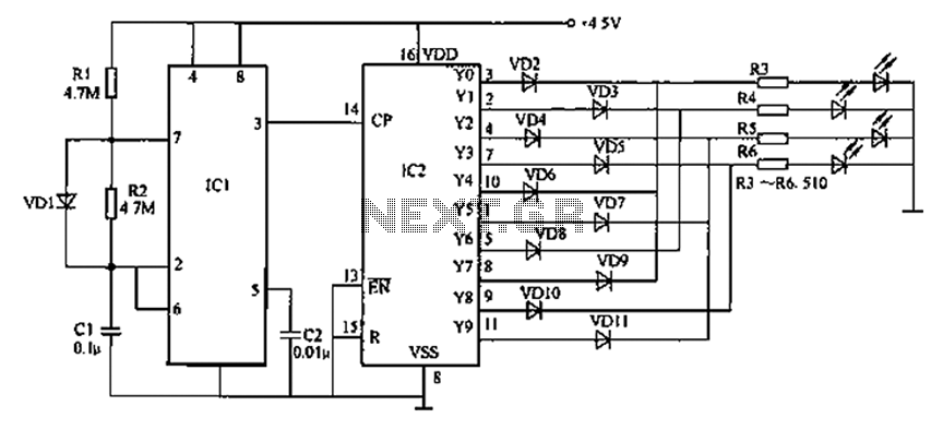
Protection elements such as diodes may be included in the circuit to prevent reverse current flow from the battery back to the solar panel during low light conditions. This ensures that the battery does not discharge through the solar panel, maintaining the charge stored within the battery.
Overall, this solar battery charger circuit is an efficient solution for renewable energy applications, providing a sustainable method for charging lead-acid batteries using solar power.Solar battery charger schematic & description. This solar battery charger circuit can charge 12v lead acid battery or sla battery. .. 🔗 External reference
Related Circuits
Prolonged reading or writing, maintaining a close distance between the eyes and the book, and insufficient lighting are primary contributors to decreased vision. This example describes a visual fatigue eliminator designed to alleviate eye fatigue and prevent myopia. The...
This compact video transmitter is highly effective for short-distance video surveillance, operating efficiently up to 100 meters. It can be paired with either a black-and-white or infrared camera module, providing excellent image quality on standard color or black-and-white televisions....
Given the variety of equipment in modern home entertainment systems, the ability to adjust the gain of both audio and video signals has become essential. This particular circuit has proven to be very useful when used alongside the General...
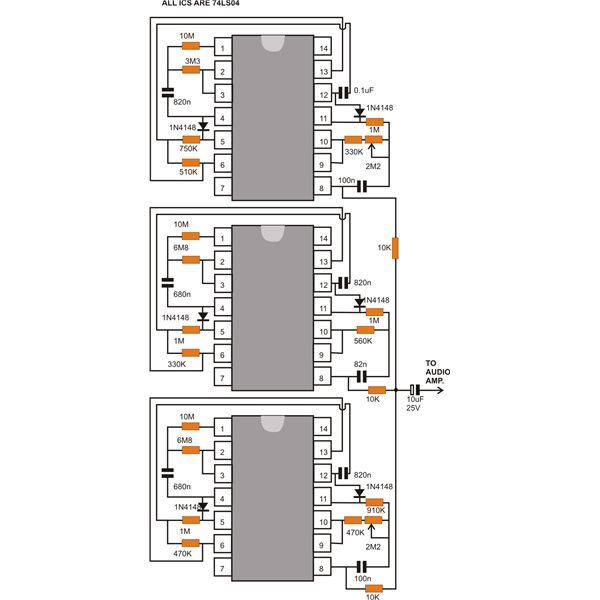
This document discusses a compact machine gun sound effect generator circuit. Once constructed, it can be integrated with any audio amplifier to create a realistic war-like simulation. This small hobby project is suitable for all electronics enthusiasts and generates...
Model Railroader is the world's largest magazine on model trains and model railroad layouts. It offers assistance for both beginners and advanced enthusiasts across all model railroading scales, including layout track plans, product reviews, news, and forums. Model Railroader magazine...
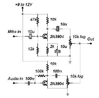
This two-channel audio mixer utilizes 2N3904 transistors to create two preamplifiers. The first preamplifier is designed for high gain, suitable for microphone input, while the second preamplifier allows for control over the audio level input. The audio mixer requires...