
Solar Charger Monitor Circuit

The described add-on circuit serves as a visual indicator for the charging status of a battery connected to a solar charger. The primary function is to illuminate a red LED, which provides a clear and immediate indication of the battery's charging state.
The circuit typically consists of a voltage divider, a transistor, and the LED. The voltage divider is connected across the battery terminals to monitor the voltage level. When the solar charger is operational and the battery is receiving charge, the voltage across the battery will rise above a predetermined threshold. This change in voltage is detected by the transistor, which acts as a switch.
When the transistor is activated, it allows current to flow through the red LED, causing it to light up. The choice of a red LED is significant, as red is often associated with alertness, making it an effective choice for indicating charging status.
In addition to the LED and transistor, the circuit may also include a resistor to limit the current through the LED, ensuring it operates within safe parameters. The design should also consider the power rating of the components to withstand the maximum expected current from the solar charger.
Overall, this simple yet effective circuit enhances the functionality of a solar charger by providing a straightforward visual cue regarding the battery's charging condition, thereby aiding users in monitoring the solar charging process.This add on circuit can be attached to the solar charger to see whether the battery is charging or not. It lights a Red LED to indicate that the battery is.. 🔗 External reference
Related Circuits
This operational amplifier (opamp) is available at a low cost. The AD8099 is a very fast opamp with a slew rate of 1600 V/µs and features high-impedance inputs with low input capacitance. Its bandwidth is sufficiently large that at...

This circuit is a simple -5V power supply using a 555 timer, designed for low-power analog applications involving FET operational amplifiers. The circuit converts +5V to -5V to create a dual power supply. It operates as a 555 astable...
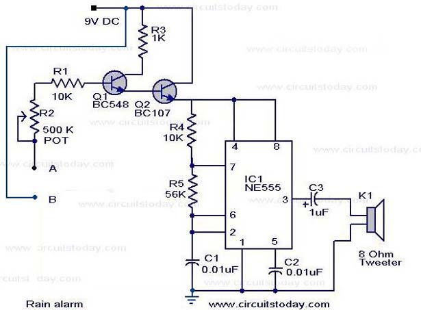
The operation of the rain alarm circuit is explained in detail. The rain alarm project is outlined along with a circuit diagram. The rain alarm circuit is designed to detect the presence of rain and alert users through an audible...

This circuit generates inaudible ultrasound to create a barrier across an entry point. When the circuit detects a disruption in the sound barrier, it triggers a loud alarm to indicate the entry of a person. This system can be...
A minimum number of parts yields a compact switching converter that can provide sufficient voltage to drive white LEDs. The resulting lamp is much more efficient, in terms of lumen hours per pound of battery, than incandescent bulbs, and...
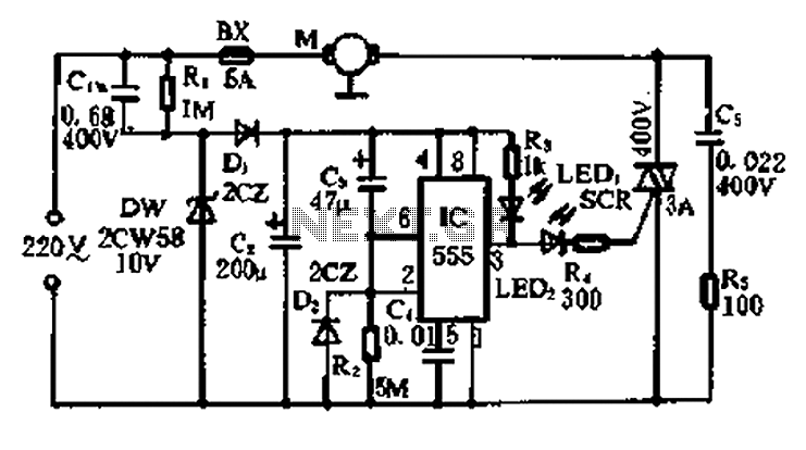
A 5-minute circuit can continue to operate during a power outage, providing protection for the refrigerator. The refrigerator power protection circuit, designated as 1136, includes a power transformer that converts 220V voltage through a rectifier bridge (VD1). This setup...