
Solar Joule Thief Circuit Project

This project combines the classic charm of a steam engine with the innovative Joule Thief circuit, creating a unique carousel that operates efficiently. The steam engine serves as the primary source of mechanical power, driving the carousel's rotation. The Joule Thief circuit, a simple boost converter, is employed to extract energy from low-voltage sources, such as depleted batteries or small solar cells, to power the lighting or electronic components of the carousel.
The steam engine consists of a boiler, a piston, and a flywheel, which converts steam pressure into mechanical motion. The carousel itself is mounted on a rotating platform, which can be designed to accommodate various decorative elements and figures that move in synchronization with the rotation.
The Joule Thief circuit typically includes a transistor, a resistor, a coil, and a diode. This circuit is capable of boosting voltages from a low level (as low as 0.9 volts) to a higher level suitable for powering LEDs or other small devices. When the Joule Thief is integrated into the carousel project, it allows for the efficient use of energy harvested from the steam engine's operation or from alternative power sources, ensuring that the lighting remains vibrant without draining the primary power supply.
In summary, this steam engine-powered carousel project not only showcases mechanical ingenuity but also incorporates modern electronic principles to enhance its functionality and sustainability. The combination of traditional steam power with the Joule Thief circuit exemplifies a creative approach to energy use in miniature engineering projects.A Very Nice Steam Engine Powered Carousel Project That Uses The Joule Thief. 🔗 External reference
Related Circuits
The Zener diode may not be providing sufficient current in its breakdown state to activate the transistor. Removing resistor R2 did not resolve the issue. The Zener's voltage selection could be too high, potentially preventing it from regulating the...
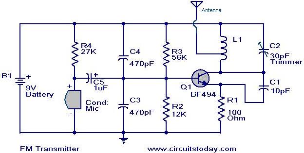
The MK484 AM receiver circuit is a simple design based on the MK484 AM receiver IC from Rapid Electronics Ltd. The MK484 is a monolithic integrated circuit that incorporates all necessary sections of an AM receiver, including an RF...
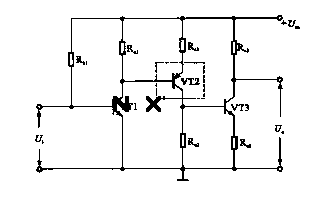
A multi-stage DC-coupled amplifier circuit utilizes NPN type transistors. Each stage is designed to achieve an appropriate operating point at the base, resulting in a stepwise increase in collector potential, which subsequently reduces the final output voltage range. To...
A project of a 555 tester circuit, the circuit will start blinking LEDs when power is applied, which will indicate that the IC is working correctly. The 555 tester circuit is designed to verify the operational status of the 555...
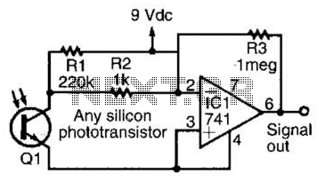
This simple amplifier is compatible with nearly any phototransistor. Although the 741 operational amplifier is designed for use with a split supply, it can also function effectively with a single-sided supply. The described amplifier circuit utilizes the 741 operational amplifier...

This LED circuit replicates the initial LED sequence currently utilized by FISA for Formula One racing. It can also be employed with slot car sets, such as HO scale AFX, Life Like, or Tyco sets, or used in communication-controlled...