
Solar Powered Motor

The circuit leverages diodes to replace traditional pull-up resistors, which enhances efficiency by reducing power consumption. The isolation of the DC load from the trigger circuit is crucial for preventing feedback that could lead to erratic motor operation. This is achieved through the use of junction drops, which help manage voltage levels, and a 10nF capacitor that acts as a filter to smooth out any fluctuations in the signal.
The concern regarding excessive power from the solar cell is valid, as it can lead to unintended motor activation. To address this, a 100K ohm resistor is strategically placed in series with the solar cell. This resistor acts as a current limiter, ensuring that the voltage and current supplied to the motor remain within acceptable levels, thus preventing continuous operation or overheating.
In summary, the combination of diodes, a capacitor, and a series resistor creates a robust circuit design that effectively manages power levels, enhances performance, and ensures reliable operation of the motor under varying conditions. This design approach is particularly beneficial in solar-powered applications where fluctuating power levels can pose challenges.By using diodes in place of pull up resistors, and by isolating the DC load from the trigger circuit via junction drops and the 10nF capacitor. If there is too much power comming from the solar cell then the motor might run too often or even continuously.
You can avoid this by putting a 100K ohm resistor in serieswith the solar cell. 🔗 External reference
Related Circuits
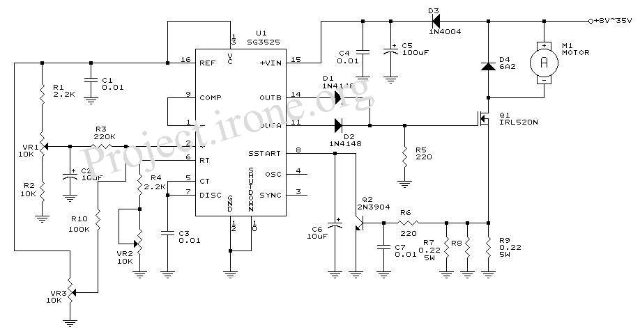
The circuit diagram is designed for precise control of DC motors. It converts DC voltage into a series of pulses, where the duration of each pulse... The circuit utilizes a pulse-width modulation (PWM) technique to regulate the speed and torque...
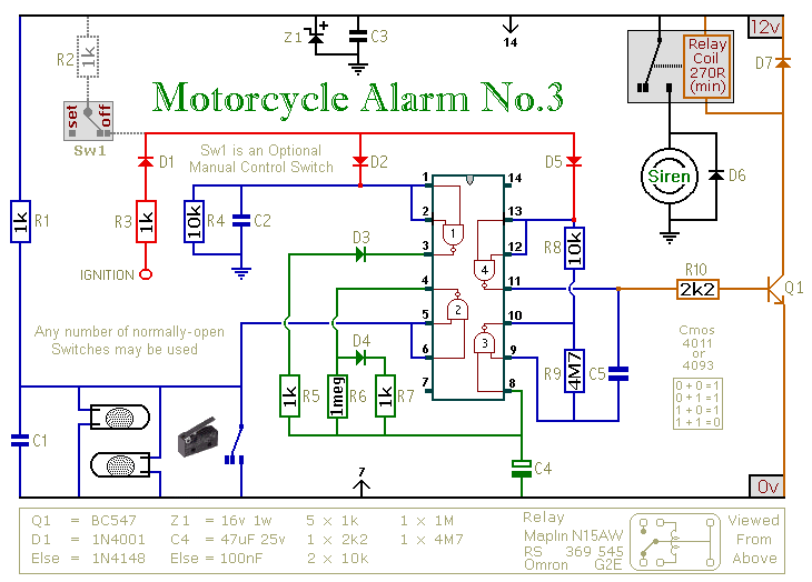
This circuit provides an intermittent siren output with an automatic reset feature. It can be operated manually through a key-switch or a hidden switch, and it can also be configured to activate automatically when the ignition is turned off....
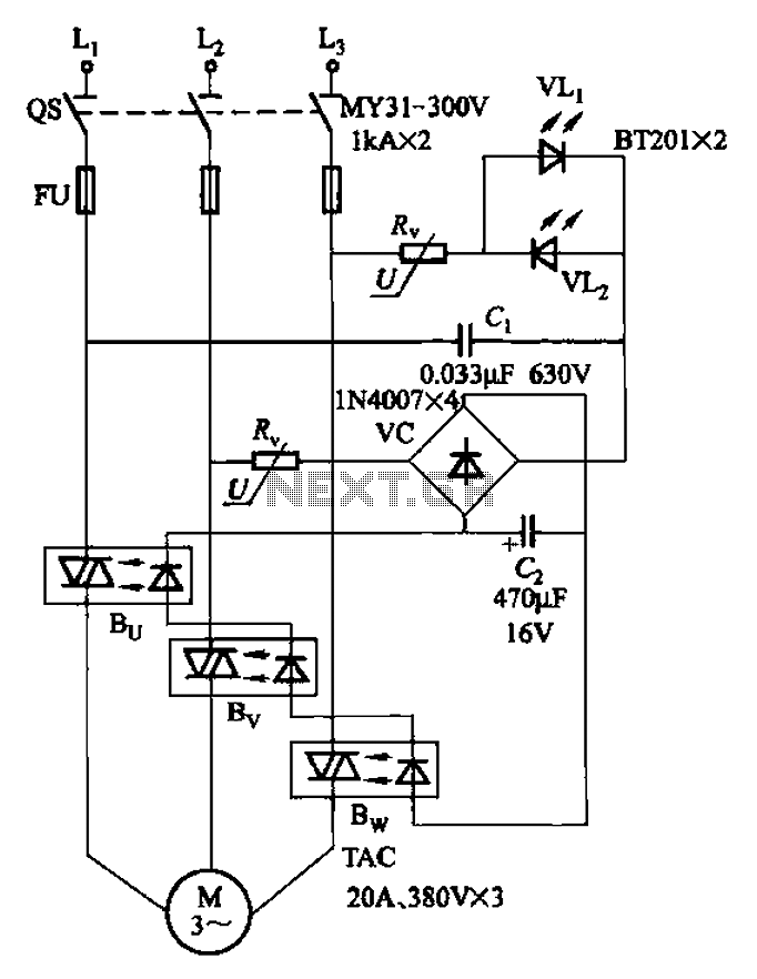
The circuit depicted in Figure 3-93 is integrated with an optical phase sequence protection relay. The circuit in question is designed to provide phase sequence protection using an optical relay mechanism. Optical phase sequence protection relays are crucial in applications...
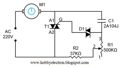
This is a simple ceiling fan regulator circuit diagram used to control the speed of a ceiling fan. In other words, it is an AC motor speed controller circuit that regulates the speed of an AC motor (Ceiling Fan)....
The SM5021 series consists of crystal oscillator module ICs fabricated using NPC's Molybdenum-gate CMOS technology. These ICs integrate high-frequency, low current consumption oscillator and output buffer circuits. They feature highly accurate thin-film feedback resistors and high-frequency capacitors, which eliminate...
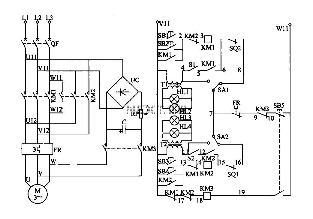
The electric valve control circuit consists of three main parts: the main lines, control lines, and power consumption brake line. The main circuit includes a power switch (QF), three-phase AC contactors (KM1, KM2), a thermal relay (FR), and a...